


KinCony E24v3 24-Channel RS485 Modbus Relay Module | Relay Modules Removable
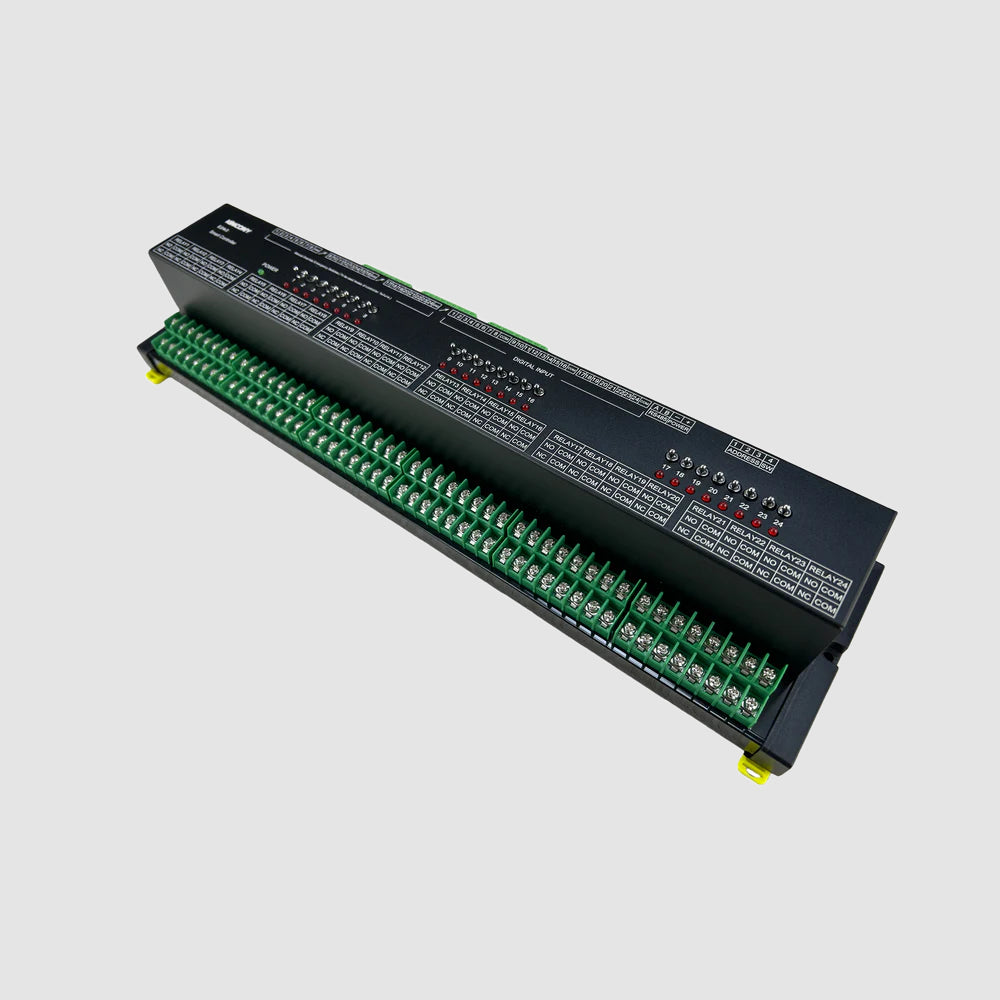
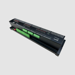
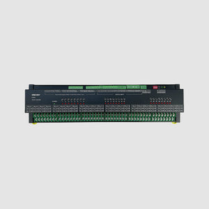
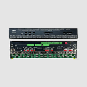
Meet the E24v3 Module: a high-capacity, industrial-grade RS485 Modbus relay module built for reliable, large-scale control. Powered by an ARM CPU, this 24-channel powerhouse features pluggable OMRON® relays, extendable manual override buttons (up to 500 meters), and flexible 12/24V control logic. Designed as a dependable slave device for PLCs, building automation systems, or any Modbus master, the E24v3 delivers robust 16A switching across 24 channels in a rugged DIN-rail form factor. Whether you're expanding an existing system or building a new industrial control network, the E24v3 is the reliable workhorse you need.
Why You'll Love This Controller
✔ High-Capacity Industrial Modbus Slave
Designed as the perfect team player in any automation network. With 24 channels, standard Modbus RTU protocol ensures easy integration with PLCs, SCADA systems, building management controllers, and even home automation platforms like Home Assistant (via ESPHome Modbus controller).
✔ True Redundancy with Extendable Manual Override
A standout feature for critical applications. Place physical control buttons up to 500 meters away for a genuine automation bypass—essential loads can be manually operated even if the entire control network or master controller fails.
✔ Ultimate Flexibility in Control Logic
Three ways to command your relays—Modbus for centralized automation, direct HIGH/LOW level signals for simple hardwired control, or manual buttons for local override. The E24v3 adapts to your system architecture, not the other way around.
✔ Built for Harsh Industrial Environments
With a -40°C to +55°C operating range, OMRON® relays rated for millions of operations, and robust construction, this module delivers decades of reliable service in demanding settings like factories, greenhouses, or outdoor installations.
✔ Maintenance-Friendly Pluggable Relays
When a relay eventually reaches end-of-life after years of service, replace it in seconds—no soldering, no board replacement, no extended downtime. Your system stays operational while maintenance is performed.
✔ Simple Hardware Configuration
The intuitive DIP switch system makes Modbus addressing quick and error-free. Set your address, enable communication, and you're online—no complex software setup or programming required.
Among other outstanding features are the following:
-
Extendable Manual Override Buttons: All 24 onboard buttons can be extended via cable up to 500 meters, enabling centralized physical control from anywhere in your facility—a true automation bypass feature for ultimate system redundancy.
-
Pluggable OMRON® Relays: High-quality 16A SPDT relays (COM/NO/NC contacts) can be individually replaced without soldering, drastically reducing downtime and simplifying long-term maintenance.
-
Flexible Triple-Mode Control: Operate via RS485 Modbus commands for centralized automation, direct HIGH/LOW level signals (12/24V) for hardwired simplicity, or manual buttons for local override—choose the method that best suits your application.
-
Industrial-Grade Durability: Engineered for harsh environments with an extended operating temperature range of -40~55°C and relay ratings of 5 million+ mechanical / 100,000+ electrical operations.
-
Simple Addressing with DIP Switch: 4-bit DIP switch enables easy hardware configuration of Modbus address (bits 1-3) and RS485 communication control (bit 4)—no software or programming required.
- Versatile Digital Inputs: Supports two wiring methods (trigger HIGH or LOW) for connecting sensors, switches, or external control signals directly to the module.
Technical Specifications:
| Category | Specification |
|---|---|
| Core Processor | Cortex-M series ARM CPU |
| Digital Outputs | 24× OMRON® SPDT relays (G2R-1-E) ▪ Contact: COM, NO, NC ▪ Max load: 250 VAC, 16 A per channel ▪ Mechanical Life: >5 million times ▪ Electrical Life: >100,000 times (20 times/min) |
| Analog Inputs | N/A |
| Digital Inputs | 24× manual control buttons (on-board) ▪ Support for external extension (up to 500m cable) |
| Digital I/O (GPIO) | N/A |
| Wireless Connectivity | N/A |
| IoT Platform | Compatible with Home Assistant via ESPHome (using RS485 Modbus controller) |
| Wired Connectivity | ▪ RS485 (standard Modbus protocol) |
| Onboard Peripherals | ▪ 4-bit DIP switch (for RS485 address and communication enable) |
| Power Supply | 12 VDC or 24 VDC (coil voltage) ▪ Consumption: 0.53W per relay |
| Environmental | ▪ Operation Temperature: -40~55℃ |
| Dimensions | 410 × 105 × 73 mm |
| Mounting | 35 mm DIN rail (EN 60715) |

I. Firmware Options and Features
| Solution | Ideal For | Key Advantages |
|---|---|---|
| 1. KCS v3 Firmware (Recommended) | Beginners / Zero-Code Users | ✔ Auto-detects Home Assistant via MQTT (no config files) ✔ Works with Tuya App + Alexa/Google Voice Control ✔ Local IFTTT automation (no internet needed) ✔ 2-year free KinCony Cloud (official store only) ✔ Apple HomeKit support (one-tap setup) |
| 2. ESPHome Firmware | Home Assistant Enthusiasts | ✔ Full open-source customization ✔ Web UI + HA deep integration ✔ Full YAML examples |
| 3. Tasmota Firmware | Open-Source Community | ✔ Massive plugin ecosystem ✔ MQTT/Web control + rule engine |
| 4. Arduino/ESP-IDF Custom Code | Developers | ✔ Full Arduino demos ✔ Supports MicroPython/ESP-IDF |
| 5. Hybrid Setup (Best Practice) | Advanced Users | Tuya App (remote via internet) + Home Assistant (local via LAN) – Security + convenience |
II. Technical Resources by Product
Direct links to pin definitions, ESPHome configurations, Arduino demo source codes, and KCS firmware. All open-source and maintained on GitHub.
| Model | KCS Firmware | Pin Definitions | ESPHome (YAML) | Arduino Demos |
|---|---|---|---|---|
|
F4
4‑ch relay · 4 inputs
ADS1115 |
📦 kcs_{KCS_VERSION}.bin | 📄 F4_pin_definition.md |
🔹 with Tuya Tuya module
🔸 without Tuya Ethernet/WiFi only
|
📁 F4/ (11 examples) |
|
F8
8‑ch relay · 8 inputs
PCF8575 |
📦 kcs_{KCS_VERSION}.bin | 📄 F8_pin_definition.md |
🔹 with Tuya Tuya module
🔸 without Tuya Ethernet/WiFi only
|
📁 F8/ (11 examples) |
|
F16
16‑ch relay · 16 inputs
PCF8575 |
📦 kcs_{KCS_VERSION}.bin | 📄 F16_pin_definition.md |
🔹 with Tuya Tuya module
🔸 without Tuya Ethernet/WiFi only
|
📁 F16/ (11 examples) |
|
F24
24‑ch relay · 24 inputs
3×PCF8575 |
📦 kcs_{KCS_VERSION}.bin | 📄 F24_pin_definition.md |
🔹 with Tuya Tuya module
🔸 without Tuya Ethernet/WiFi only
|
📁 F24/ (12 examples) |
|
F32
32‑ch relay · 32 inputs
3×PCF8575 |
📦 kcs_{KCS_VERSION}.bin | 📄 F32_pin_definition.md |
🔹 with Tuya Tuya module
🔸 without Tuya Ethernet/WiFi only
|
📁 F32/ (11 examples) |
| Model | KCS Firmware | Pin Definitions | ESPHome (YAML) | Arduino Demos |
|---|---|---|---|---|
|
T16M
16‑ch relay + 16 inputs
single I2C bus |
📦 kcs_{KCS_VERSION}.bin | 📄 T16M_pin_definition.md | 📁 T16M/ (6 examples) | |
|
T32M
32‑ch relay + 32 inputs
dual I2C bus |
📦 kcs_{KCS_VERSION}.bin | 📄 T32M_pin_definition.md | 📁 T32M/ (7 examples) | |
|
T64M
64‑ch relay + 64 inputs
dual I2C buses |
📦 kcs_{KCS_VERSION}.bin | 📄 T64M_pin_definition.md | 📁 T64M/ (8 examples) | |
|
T128M
128‑ch relay + 128 inputs
dual I2C buses |
📦 kcs_{KCS_VERSION}.bin | 📄 T128M_pin_definition.md | 📁 T128M/ (8 examples) | |
|
TA
Thermostat Adapter
|
📦 kcs_{KCS_VERSION}.bin | 📄 TA_pin_definition.md | 📁 TA/ (11 examples) |
🔸 v2 high‑precision ESPHome configs (0.001 kWh) require ARM CPU firmware ≥ V20_260305SP.
| Model | KCS Firmware | Pin Definitions | ESPHome (YAML) | Arduino Demos |
|---|---|---|---|---|
|
N10
10‑ch energy meter
|
📦 kcs_{KCS_VERSION}.bin | 📄 N10_pin_definition.md |
🔹 N10_esphome.yaml v1 (1 kWh)
🔸 N10_esphome_v2.yaml v2 (0.001 kWh)
v2 require ARM CPU firmware ≥ V20_260305SP. |
📁 N10/ (5 examples) |
|
N20
20‑ch energy meter
|
📦 kcs_{KCS_VERSION}.bin | 📄 N20_pin_definition.md |
🔹 N20_esphome.yaml v1 (1 kWh)
🔸 N20_esphome_v2.yaml v2 (0.001 kWh)
v2 require ARM CPU firmware ≥ V20_260305SP. |
📁 N20/ (5 examples) |
|
N30
30‑ch energy meter
|
📦 kcs_{KCS_VERSION}.bin | 📄 N30_pin_definition.md |
🔹 N30_esphome.yaml v1 (1 kWh)
🔸 N30_esphome_v2.yaml v2 (0.001 kWh)
v2 require ARM CPU firmware ≥ V20_260305SP. |
📁 N30/ (5 examples) |
|
N60
60‑ch energy meter
|
📦 kcs_{KCS_VERSION}.bin | 📄 N60_pin_definition.md |
🔹 N60_esphome.yaml v1 (1 kWh)
🔸 N60_esphome_v2.yaml v2 (0.001 kWh)
v2 require ARM CPU firmware ≥ V20_260305SP. |
📁 N60/ (5 examples) |
| Model | KCS Firmware | Pin Definitions | ESPHome (YAML) | Arduino Demos |
|---|---|---|---|---|
|
DM4
4‑ch digital input module
|
📦 kcs_{KCS_VERSION}.bin | 📄 DM4_pin_definition.md |
🔸 without Tuya Ethernet/WiFi only
|
📁 DM4/ (11 examples) |
|
DM8
8‑ch digital input module
|
📦 kcs_{KCS_VERSION}.bin | 📄 DM8_pin_definition.md |
🔸 without Tuya Ethernet/WiFi only
|
📁 DM8/ (11 examples) |
|
DM16
16‑ch digital input module
|
📦 kcs_{KCS_VERSION}.bin | 📄 DM16_pin_definition.md |
🔹 with Tuya Tuya module
🔸 without Tuya Ethernet/WiFi only
|
📁 DM16/ (11 examples) |
|
DM32
32‑ch digital input module
|
📦 kcs_{KCS_VERSION}.bin | 📄 DM32_pin_definition.md |
🔸 without Tuya Ethernet/WiFi only
|
📁 DM32/ (11 examples) |
| Model | KCS Firmware | Pin Definitions | ESPHome (YAML) | Arduino Demos |
|---|---|---|---|---|
|
G1
Gateway controller
|
📦 kcs_{KCS_VERSION}.bin | 📄 G1_pin_definition.md | Not supported | 📁 G1/ (11 examples) |
|
AIO Hybrid
All‑in‑one hybrid controller
RF433 · Zigbee · IR · DAC |
📦 kcs_{KCS_VERSION}.bin | 📄 AIO_Hybrid_pin_definition.md |
🔹 with Tuya Tuya module
🔸 without Tuya Ethernet/WiFi only
|
📁 AIO Hybrid/ (13 examples) |