4.1 Index (Home)
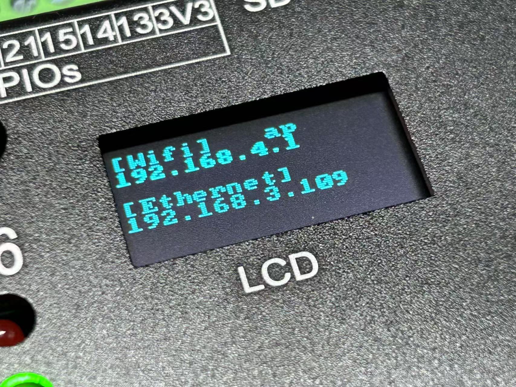
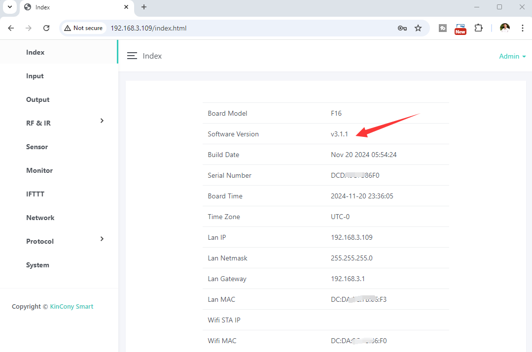
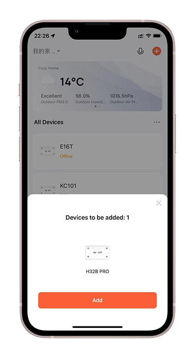
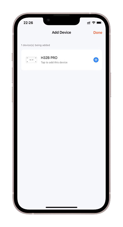
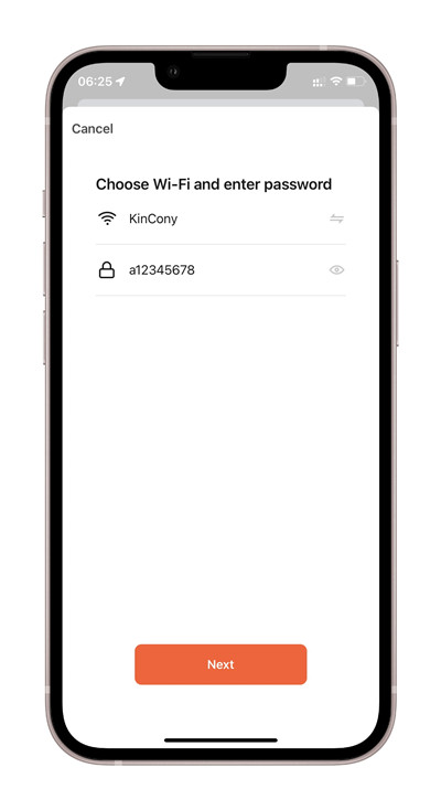
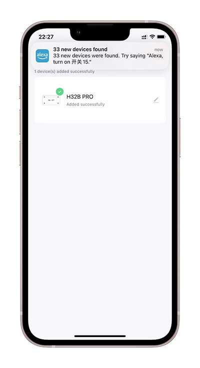
The home page displays key system parameters and network information.
4.2 Inputs
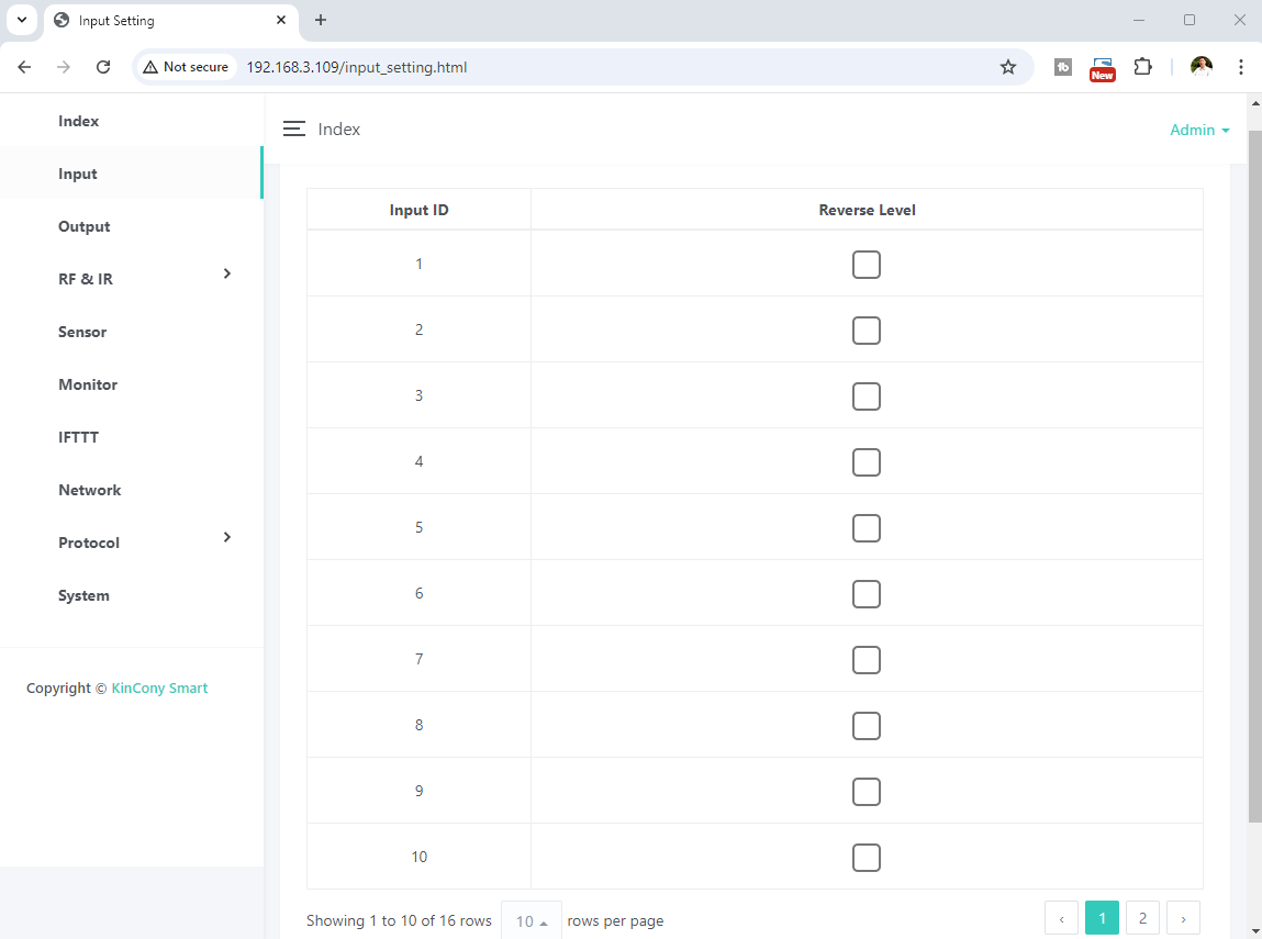
The inputs page lets you configure how each digital input port interacts with outputs. Reverse Level inverts the active state (useful for normally closed sensors). Typically, shorting an input to GND triggers it (active LOW).
4.3 Outputs
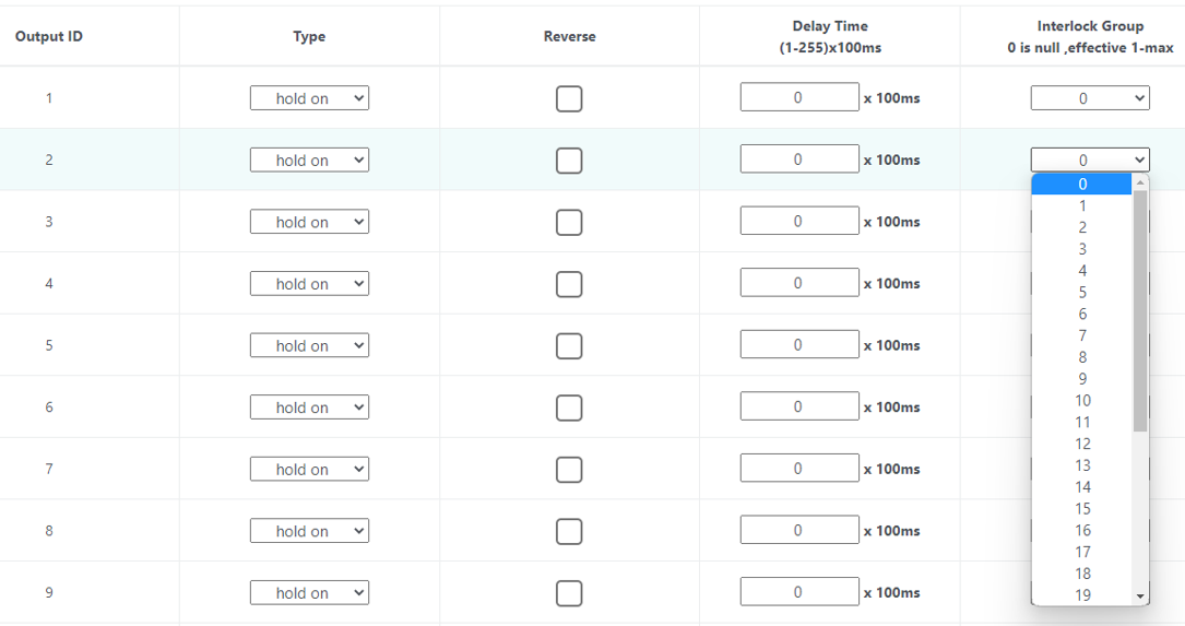
The outputs page configures the corresponding functions and parameters for each output channel.
-
Hold on: Keep the output state after reboot.
-
Delay: Auto-turn-off after a preset time (seconds).
-
Interlock group: Define mutual exclusion groups. Set to “0” to disable. If Output1 and Output2 both have group “1”, they interlock; Output3 and Output4 with group “2” form another group. Example: 64 outputs = 32 interlock groups.
4.4 RF & IR
RF Remote (433MHz)
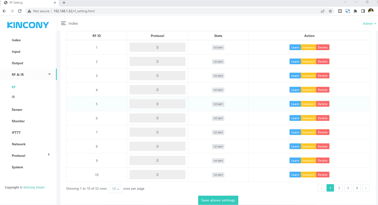
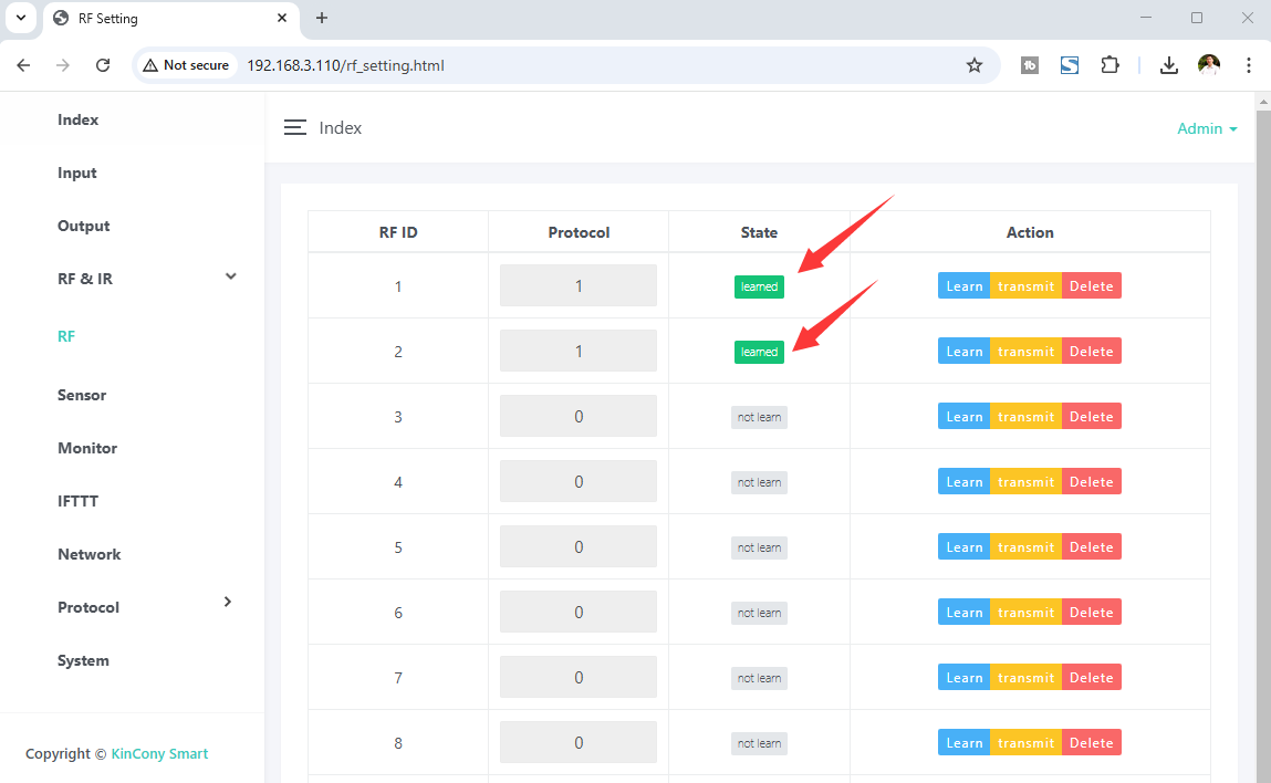
Supports "Learn", "Transmit", "Delete" RF codes, and supports EV1527, PT2262, PT2264 codes.
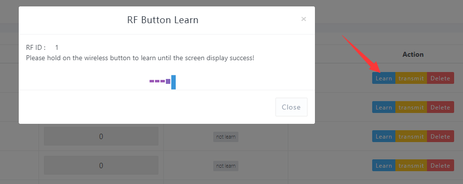
Press Learn to begin study mode, it will show a message like this:
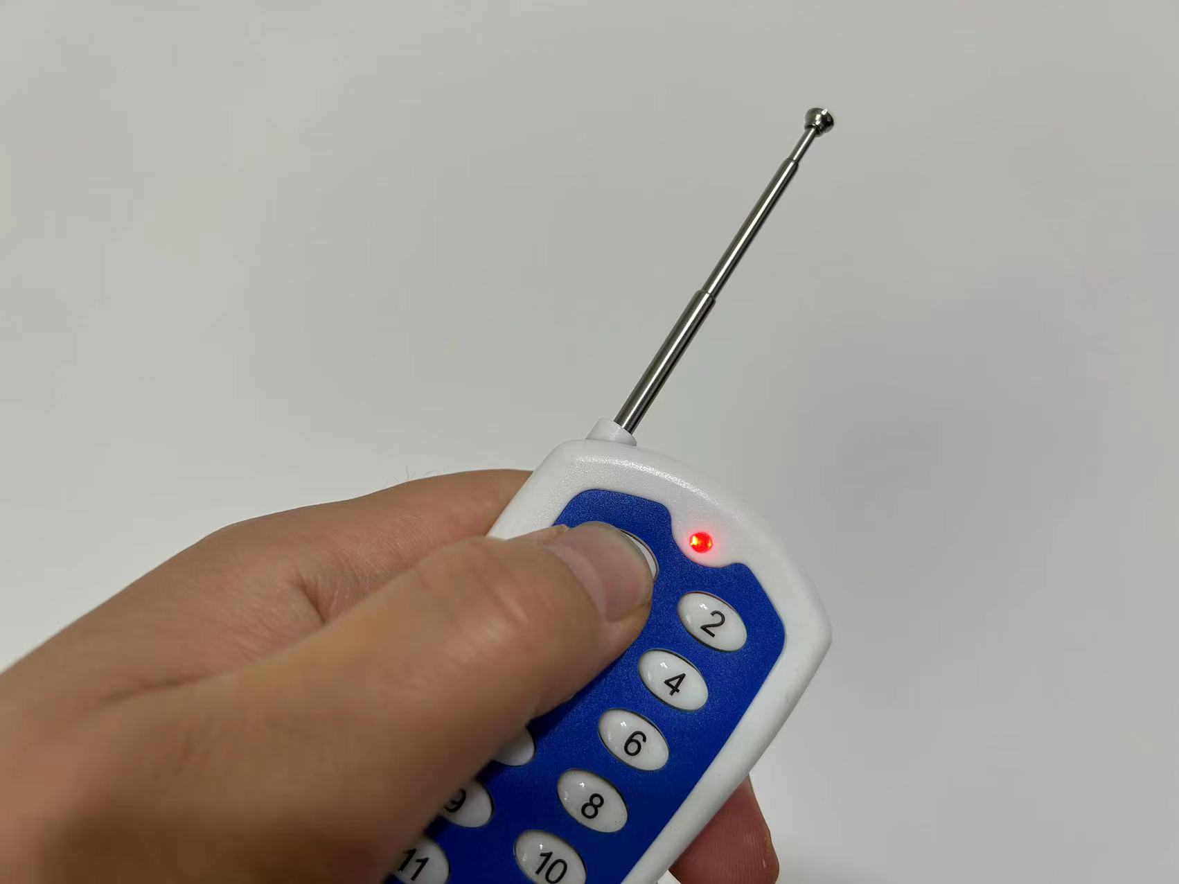
Then press a button on your remote control.
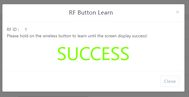
Success message:
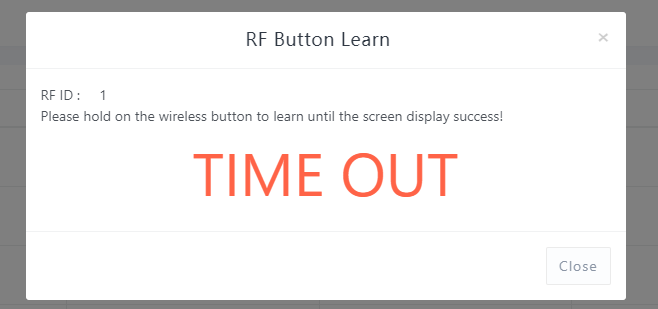
Failure or timeout:
After learning, the status will be displayed as "learned".
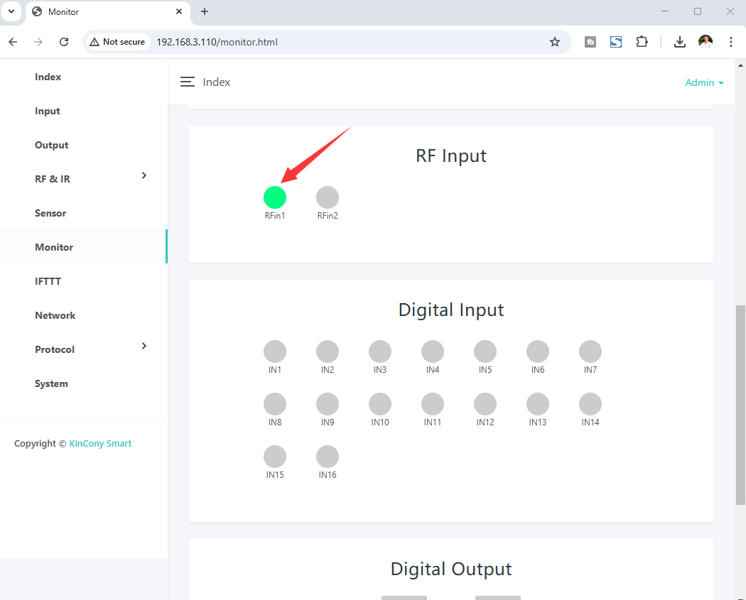
You can monitor your RF sensor state on the "Monitor" webpage. If an RF signal is received, the icon will turn GREEN.
Infrared (IR)
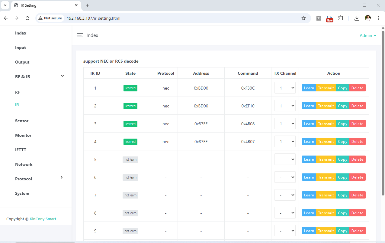
IR webpage supports "Learn", "Transmit", "Copy", "Delete" IR codes for TV, DVD, air conditioner, fans or other IR devices.
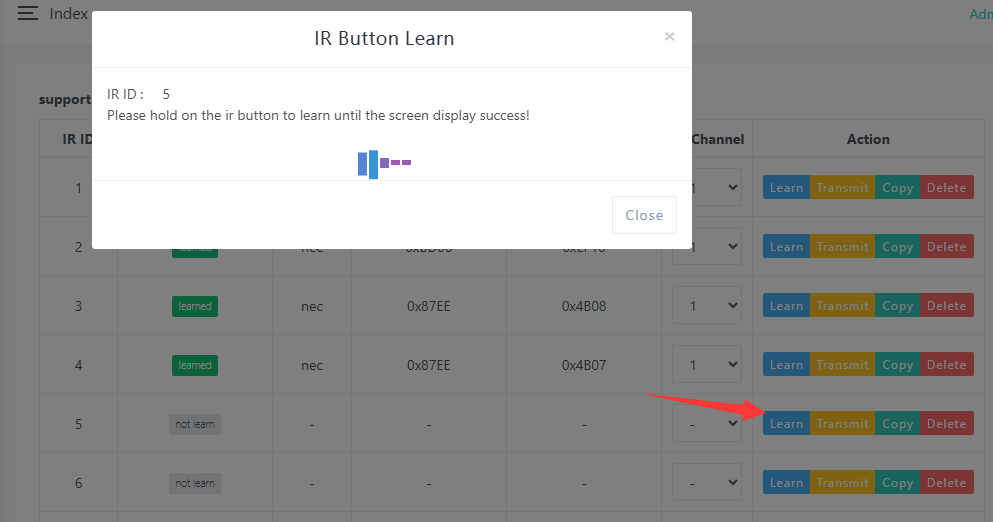
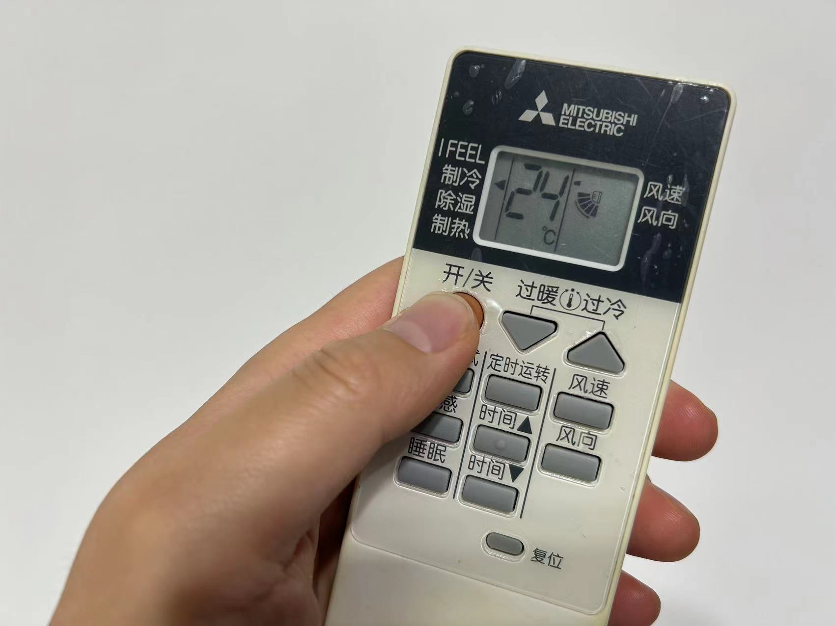
Press the blue “Learn” button to begin study mode. It will wait for you to press an IR remote button and show a message:
Then press one button on your IR remote to send a signal to the board’s IR receiver:
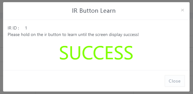
Learning success:
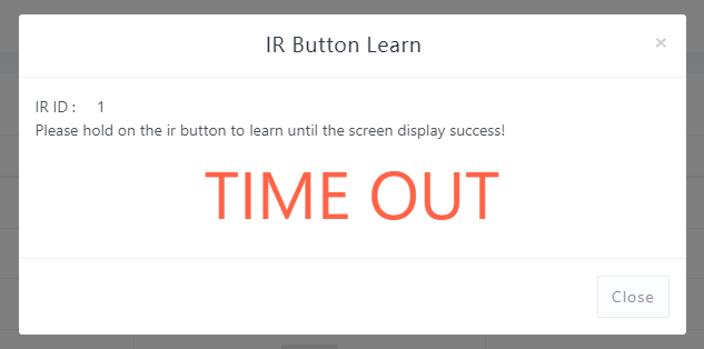
Otherwise:
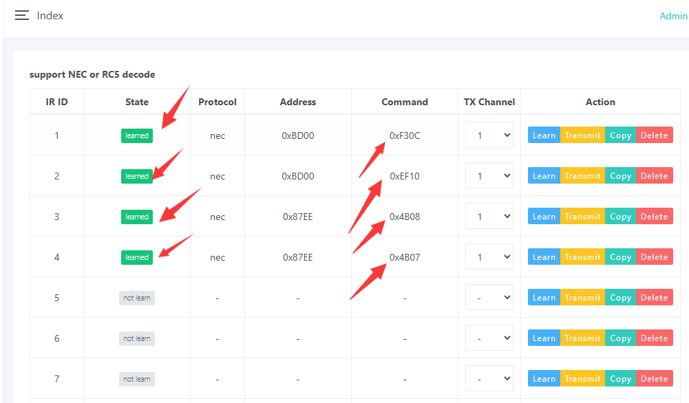
After learning, the code is saved on the controller.
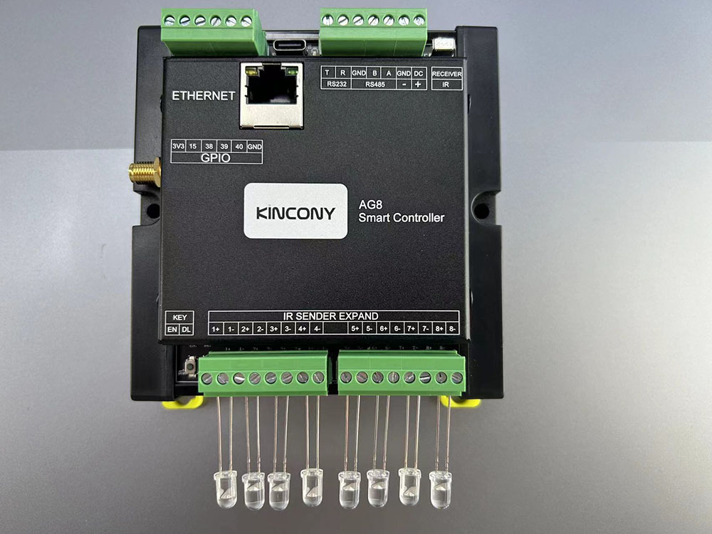
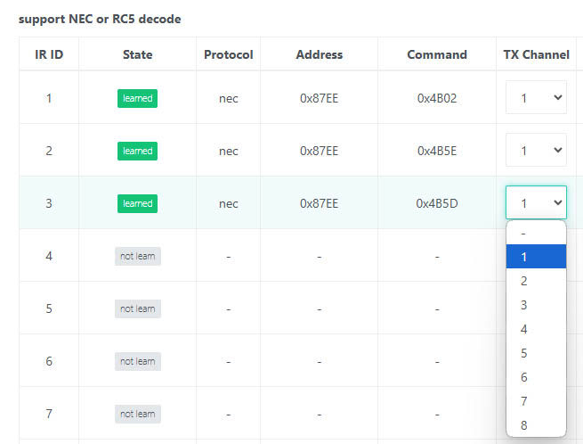
TX channel means the IR emitter ID, because some IR controllers have multiple IR emitters (e.g., our AG8 IR Controller).
TX channel selects which IR emitter sends the signal.
💡 If your remote uses NEC/RC5, the decoded signal can be used as a binary sensor. Non‑decodable protocols can still be learned and transmitted.
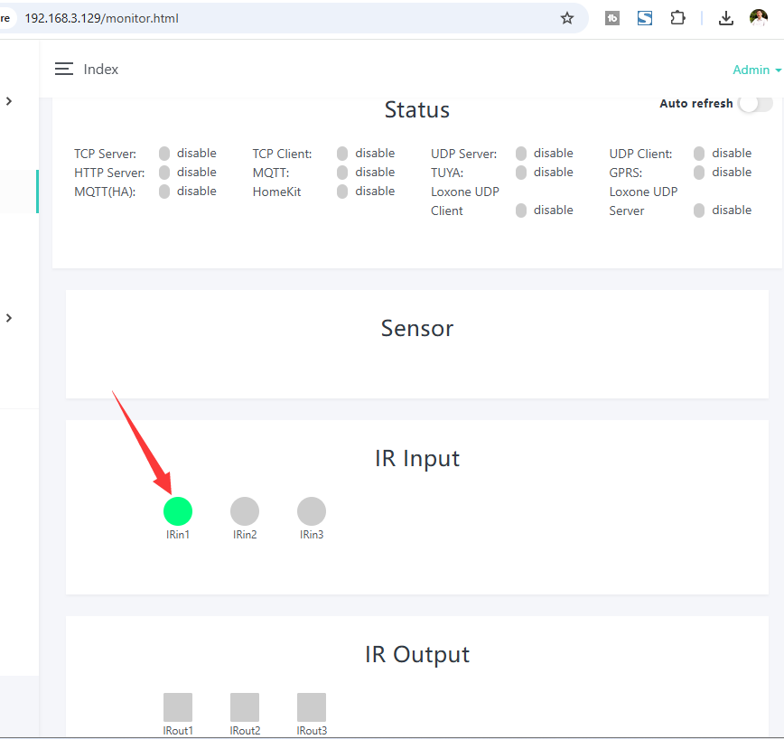
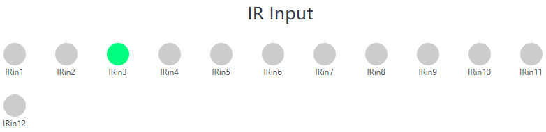
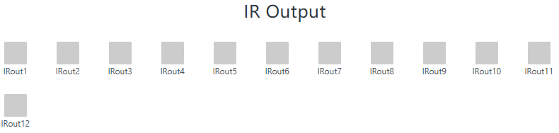
When an IR signal is received, the input item will show GREEN. You can click the "IR Output" button to manually send an IR signal.
If you want to copy an IR code to a new ID, press the "Copy" button and fill in the source IR ID number. For example, if you fill "1", the new IR ID5 will be the same as IR ID1, so you don't need to learn the IR signal again.
4.5 Sensors
The Sensors feature enables the KCS firmware to access and manage multiple sensors, allowing flexible configuration and data updates.
-
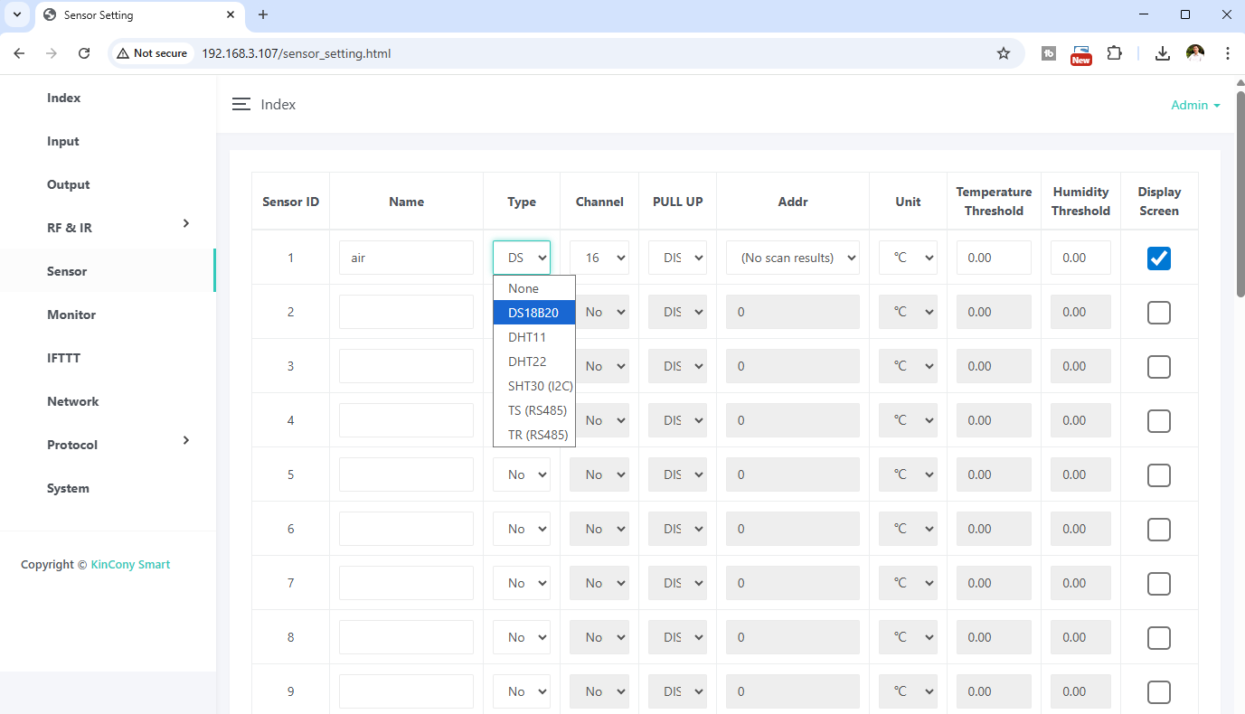
Type: Supported sensors include:
-
1-Wire: DS18B20, DHT11, DHT22, SHT30, TS, TR (on GPIO).
-
I2C: SHT30.
-
RS485: KinCony TS/TR temperature/humidity sensors.
-
PULL UP: Enable/disable internal pull‑up (if the PCB lacks external resistors).
-
Temperature/Humidity Threshold: Data updates only when the value changes beyond the threshold, reducing network traffic. Example: threshold=2°C, current 28°C → updates when new temp >30°C or <26°C.
-
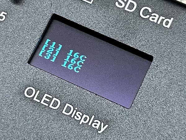
Display screen: Show sensor values on the optional OLED.
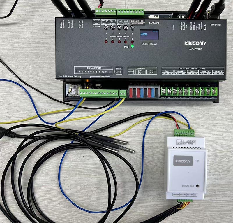
Here is a sample configuration using three DS18B20 sensors connected via a TR module, all communicating over RS485.
4.6 Monitor Dashboard
Under the Monitor feature, you can monitor the working status of all protocols, whether they are connected to a server or have a client connected.
- Real-time monitoring of the operational status of all protocols (connecting to server or client connection).
-
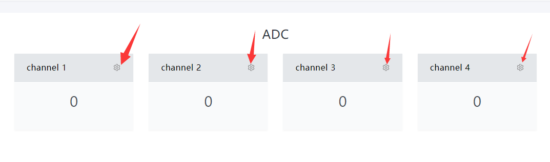
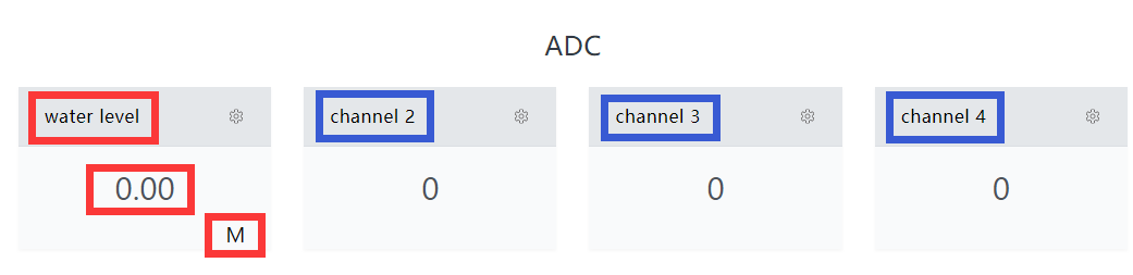
ADC (Analog to Digital): View the values of each sensor.
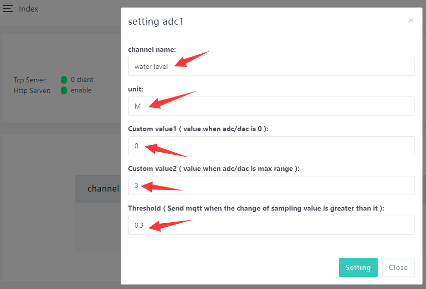
Click the gear icon to access the settings page. You can set individual sensor channel names, range, display units, and auto-report threshold for each sensor.
For example: Use a water level sensor to show you exactly how to fill out this form step by step.
Imagine you have a sensor that measures water depth from 0 to 3 meters. It sends a DC voltage signal: 0V at 0 meters, and 5V at 3 meters. Fill out the form as follows:
-
Channel Name: Type "Water Level".
-
Unit: Choose "M" (meters).
-
Custom Value 1: Enter "0" — the actual depth when sensor voltage is 0V.
-
Custom Value 2: Enter "3" — the depth when sensor voltage is 5V.
-
Threshold: Enter "0.3" if you want an alert when water level changes by more than 0.3 meters. The system will automatically send an MQTT message when the value jumps or drops by that much.
-
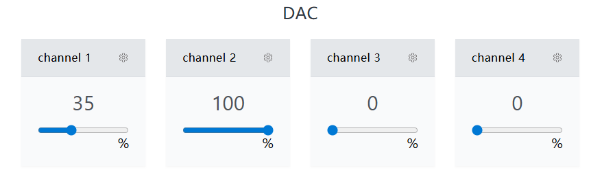
DAC (Digital to Analog): This panel monitors DAC values.
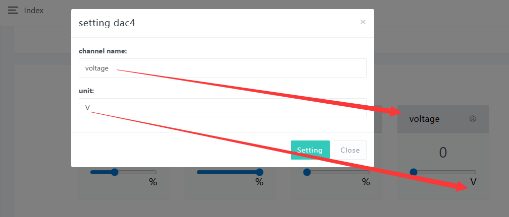
4-channel DC 0-10V output, adjustable from 0% to 100% (0-10V). You can set channel name and unit here.
-
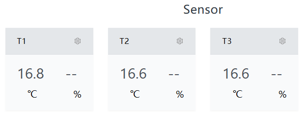
Sensor: The sensor panel is used to monitor temperature and humidity values.
-
RF Input: Control panel included.
-
IR Input: Control panel included.
-
Scene: Control panel included.
-
IR Output: Control panel included.
4.7 Automation (IFTTT)
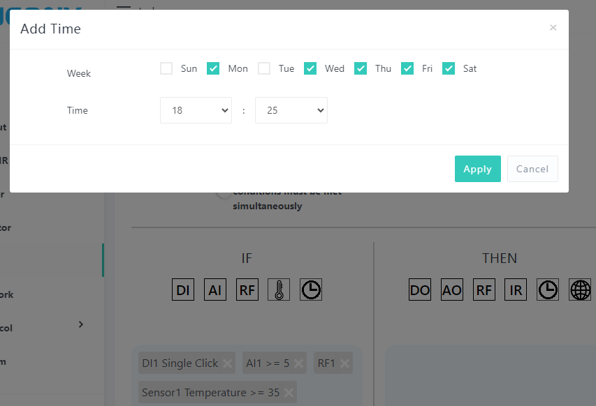
On this page, you can use the IFTTT function to set up automation programs. Click Run to test the defined program, or click Edit to go to the program editing page.
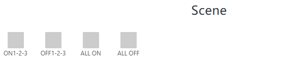
You can also find Scene Mode here. If Enabled, a scene button will be created on the Monitor webpage and automatically discovered/updated to Home Assistant via MQTT.
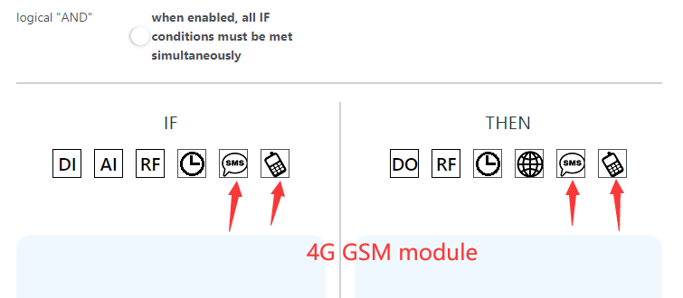
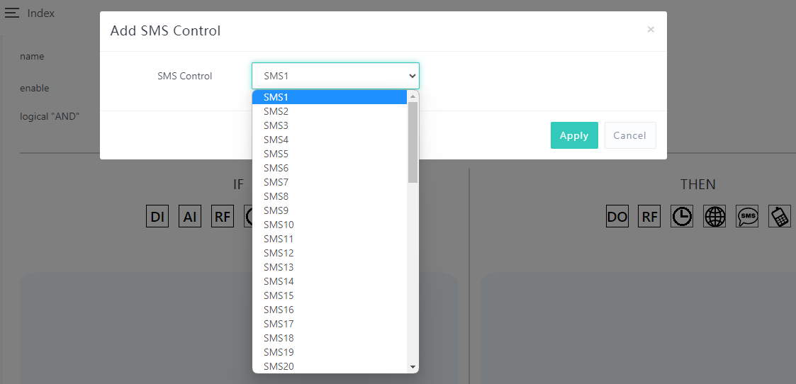
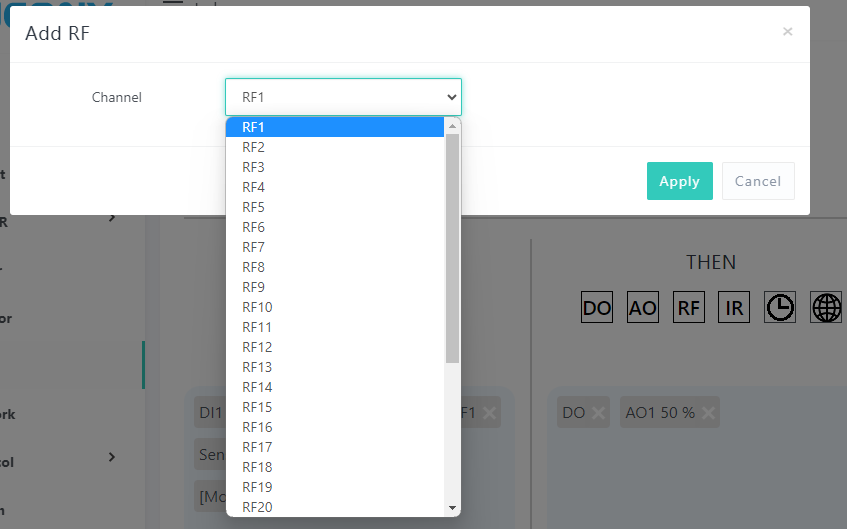
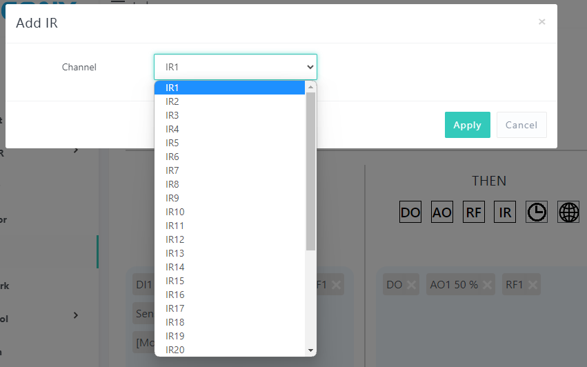
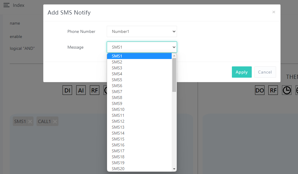
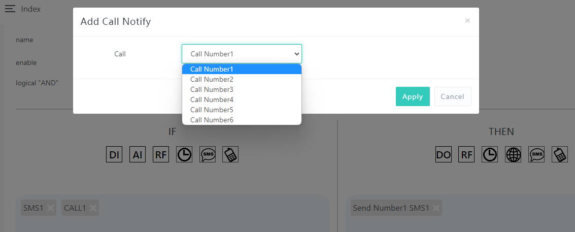
If your product model supports the 4G SIM7600 module, then there will be SMS and Voice Call icons. You can rename the automation, and enable or disable it.
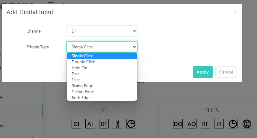
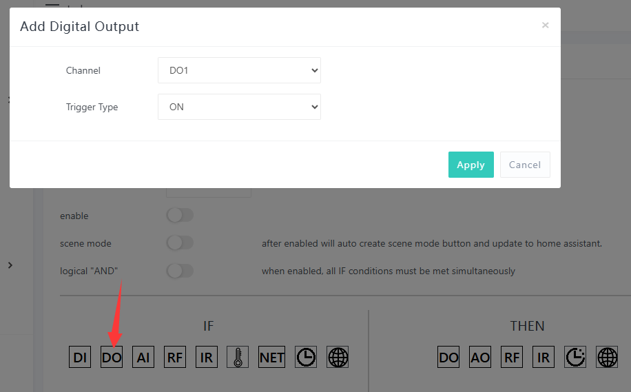
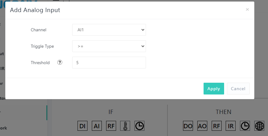
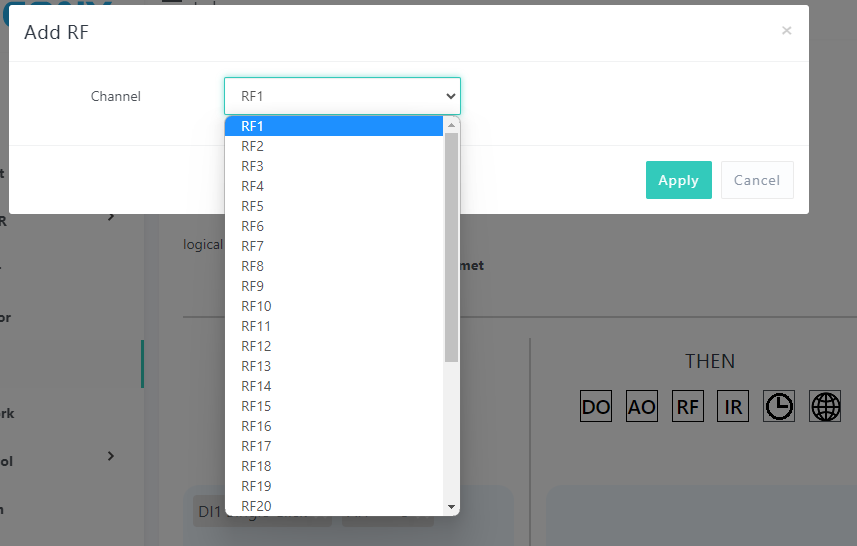
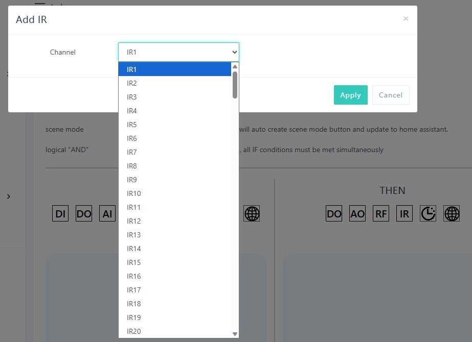
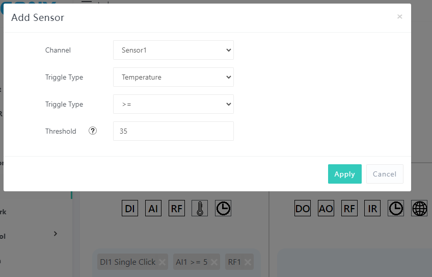
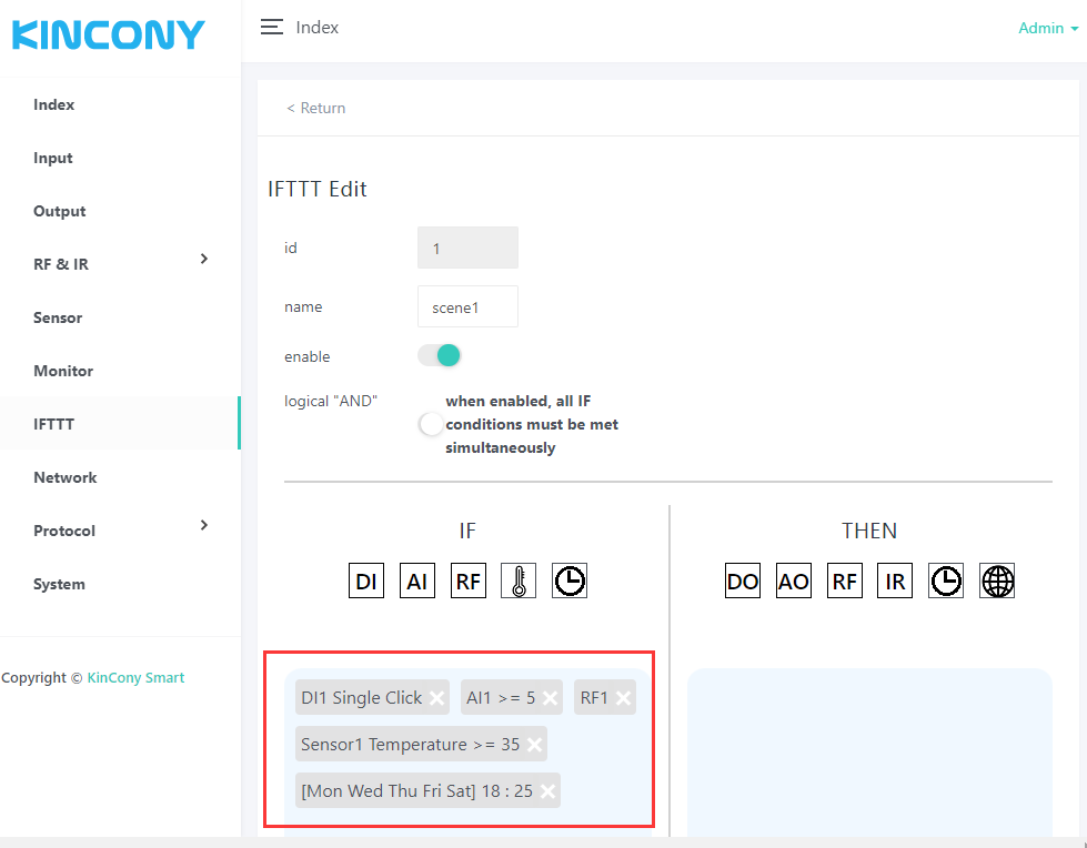
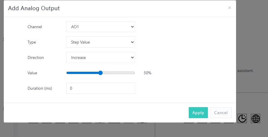
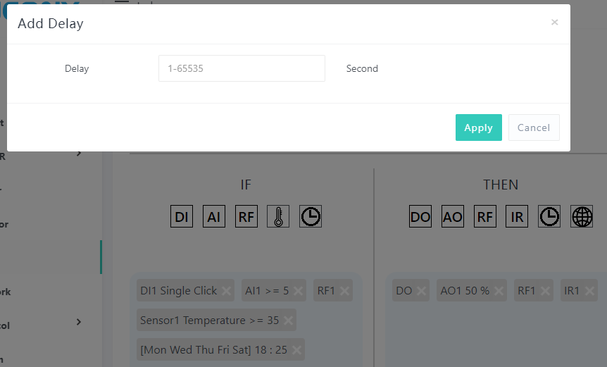
Using IF and THEN together allows you to customize the conditions of the automation.
-
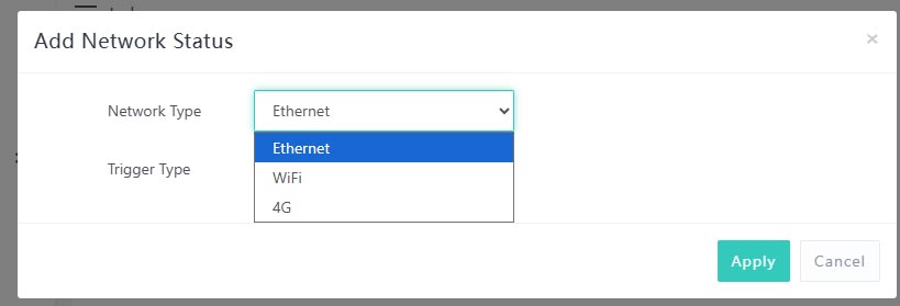
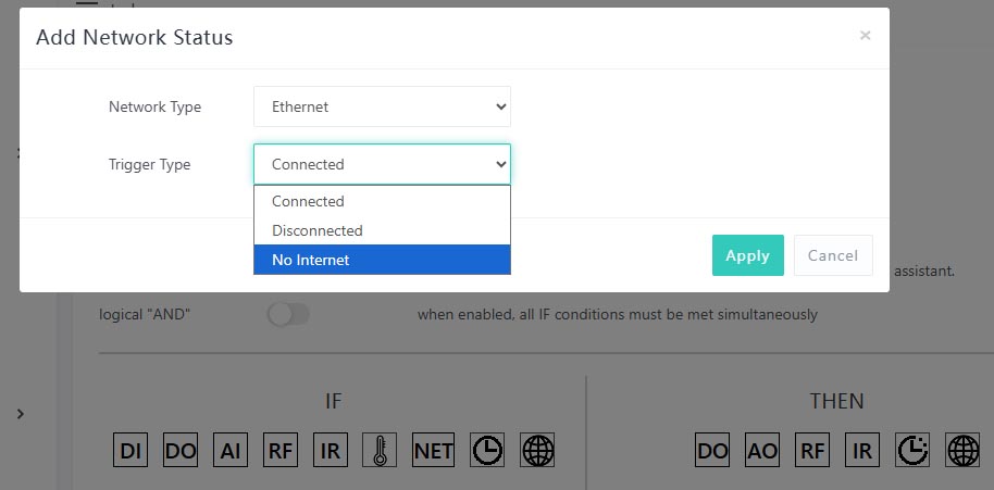
IF – Network status options:
-
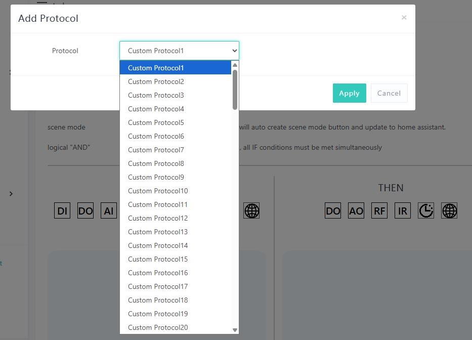
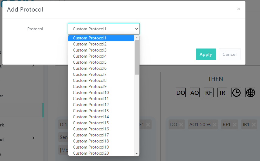
IF – Custom Protocol options:
If the Logical AND option is enabled, all If conditions must be met for the action to be executed. Otherwise, the If conditions are treated as Logical OR, and satisfying any one condition is sufficient to execute the action.
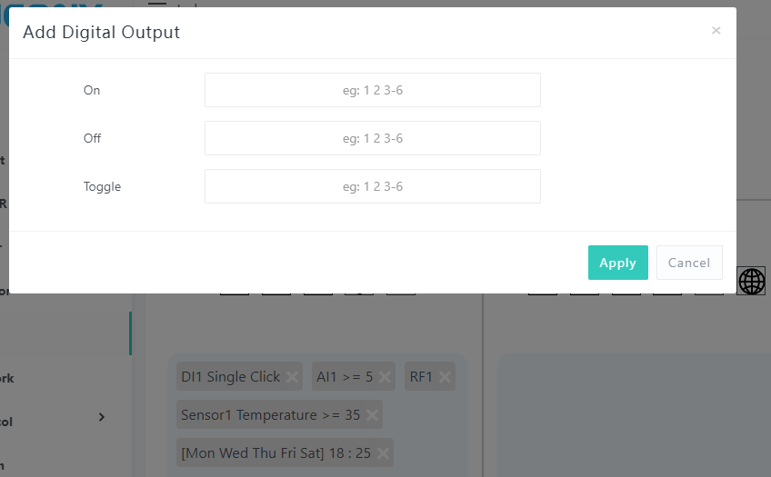
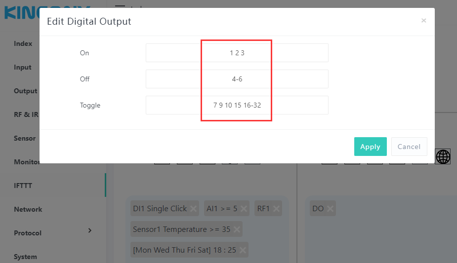
You can set them and separate with a space, for example: "1 2 3 4 5". Or using "1-5" has the same effect.
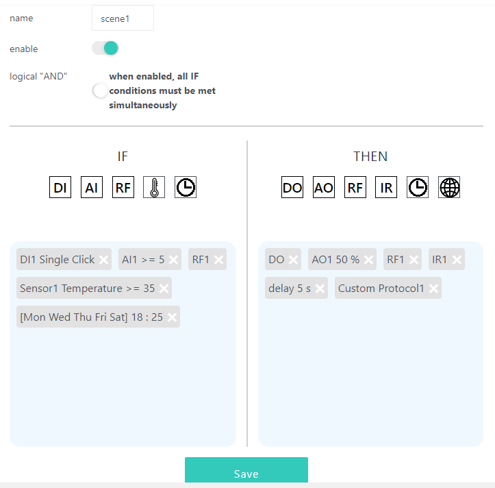
Let's take an example. Please see the image below:
The above example represents:
Turn On digital output 1, 2, 3
Turn Off digital output 4, 5, 6
7, 9, 10, 15, 16, 17, 18, 19, 20, 21, 22, 23, 24, 25, 26, 27, 28, 29, 30, 31, 32 toggle status (On→Off, Off→On).
-
THEN – Custom Protocol options:
-
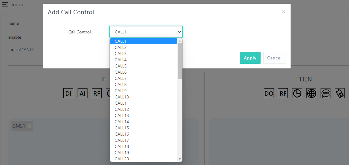
THEN – Voice Call options:
After completing all the settings, you can see all the icons under IF and THEN. You can "Save" automation (scene1) or click on an icon to modify again.
4.8 Network & GSM
The Network page provides flexible network connectivity and GSM features for your controller board.
- Ethernet & Wi-Fi Settings
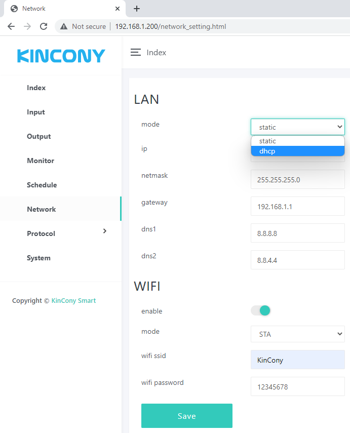
You can connect your board to the internet using either Ethernet or Wi-Fi.
-
STA Mode – The controller connects to your existing router's Wi-Fi. Just enter the SSID and password of your router.
-
AP Mode – The board itself creates a Wi-Fi hotspot. Your phone or tablet can connect directly to the board without needing a router. You can set your own SSID and password for this hotspot.
-
Auto Failover – If you set Wi-Fi to STA mode and also connect an Ethernet cable to your router, the board will use Ethernet first. If the Ethernet cable is disconnected, it will automatically switch to Wi-Fi to maintain the connection to your router. This ensures your board stays online at all times.
- GSM / 4G Module Configuration
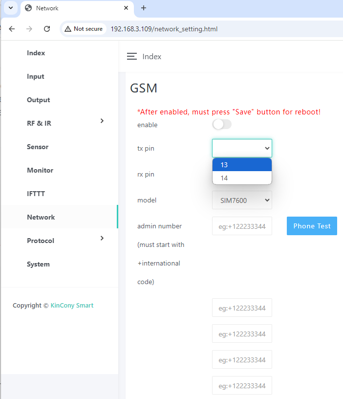
On the Network – GSM webpage, you can manage your 4G module.
-
Enable / Disable – Turn the GSM module on or off. When disabled, SMS, voice calls, and GPRS will not work.
-
Pin Assignment – Define the RXD and TXD pins for your external 4G module (e.g., KinCony G1 4G module).
-
Administrator Phone Numbers – You can add up to 6 administrator numbers. Only these numbers can use the SMS and voice call functions. (Note: The Tuya app uses GPRS and has no phone number limit.)
-
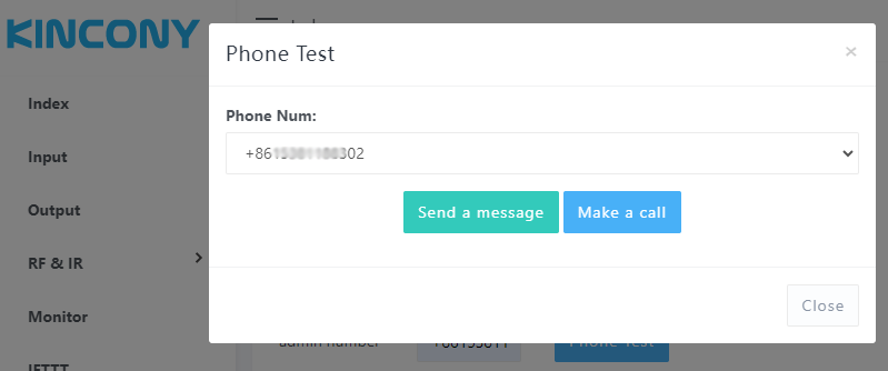
Test Functions – Select a phone number from your list, then click "Send a message" or "Make a call" to test the connection.
- Using SMS for Automation
SMS messages can be used in two ways:
-
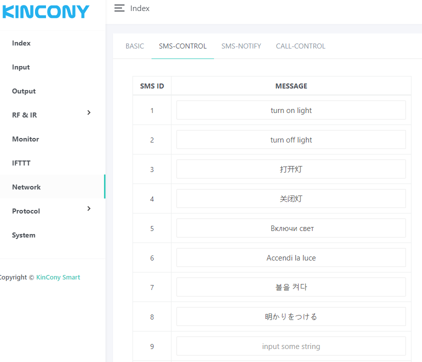
As an IF Condition – Define specific SMS content (in your local language, not just English). When the board receives a message matching that content, it can trigger an automation.
-
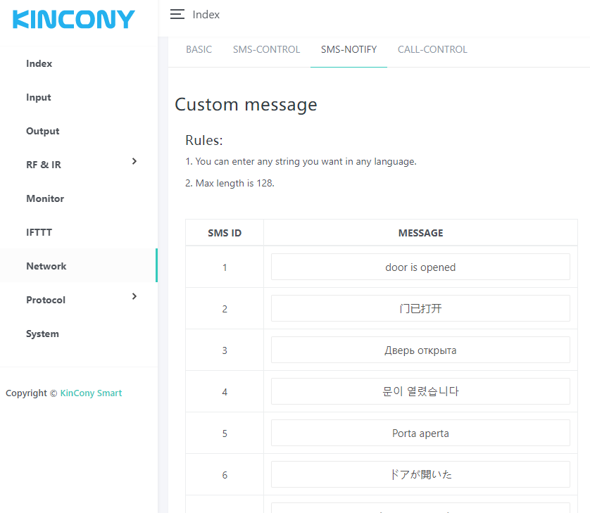
As a THEN Action – Define SMS content to send out as an alarm notification or any other alert. Again, you can write the message in your local language.
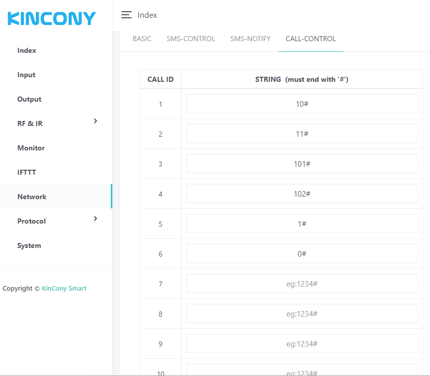
- Voice Call Control (DTMF)
You can control relays by making a voice call to the board.
- When you call the board and the call is connected, press a number followed by # (e.g., 10#).
-
Example:
- Press 10# → Turn ON relay 1
- Press 11# → Turn ON relay 2
You define these DTMF codes as IF conditions in your automation rules.
4.9 Protocols & Integrations
This page lets you send custom commands over various protocols, integrate with Apple HomeKit and Loxone, control RGBW LED strips, and more. Follow this guide to unlock its full potential.
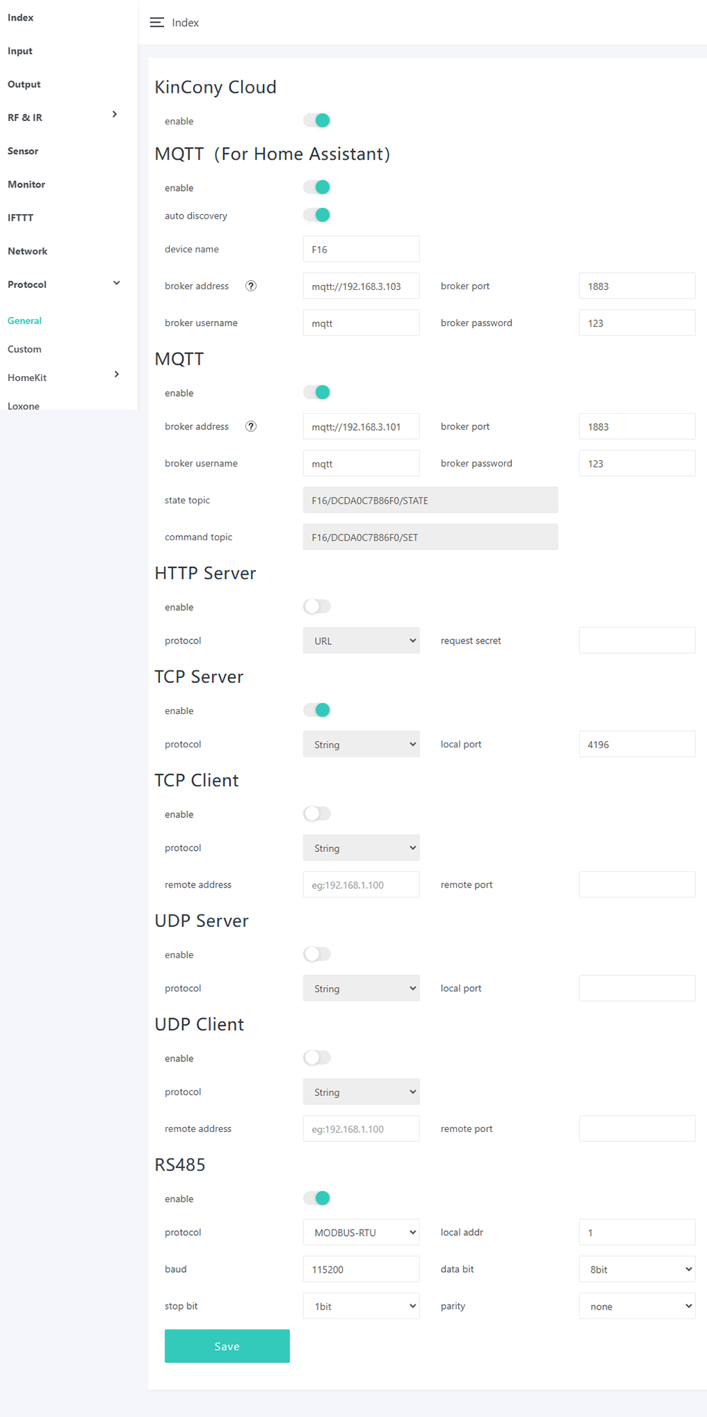
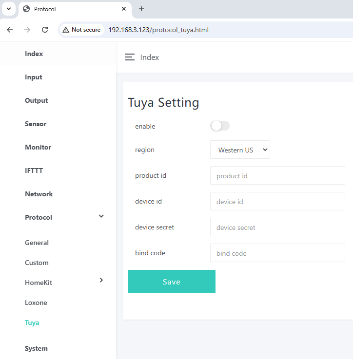
On this page, you can enable or disable different protocols as needed.
- KinCony Cloud Service
What it does:
When you enable KinCony Cloud, you can remotely control relays or monitor sensor states using any web browser over the internet – no need for port forwarding or a local VPN.
How to use:
A separate guide "How to use KinCony Cloud service" explains how to set up and use the KinCony Cloud service.
💡 This is the easiest way to access your board from anywhere without additional network configuration.
- MQTT (For Home Assistant)
What it does:
Enabling the MQTT option allows all board hardware resources (relays, sensors, inputs, outputs, etc.) to be automatically discovered by Home Assistant. You do not need to manually add any entities or write configuration files.
What you need to set:
- MQTT broker IP address
- Port (usually 1883 or 8883 for TLS)
- Username and password (if your broker requires authentication)
Why it's great:
This is the easiest way to use Home Assistant and the KinCony Cloud service simultaneously – the board communicates with both without conflict.
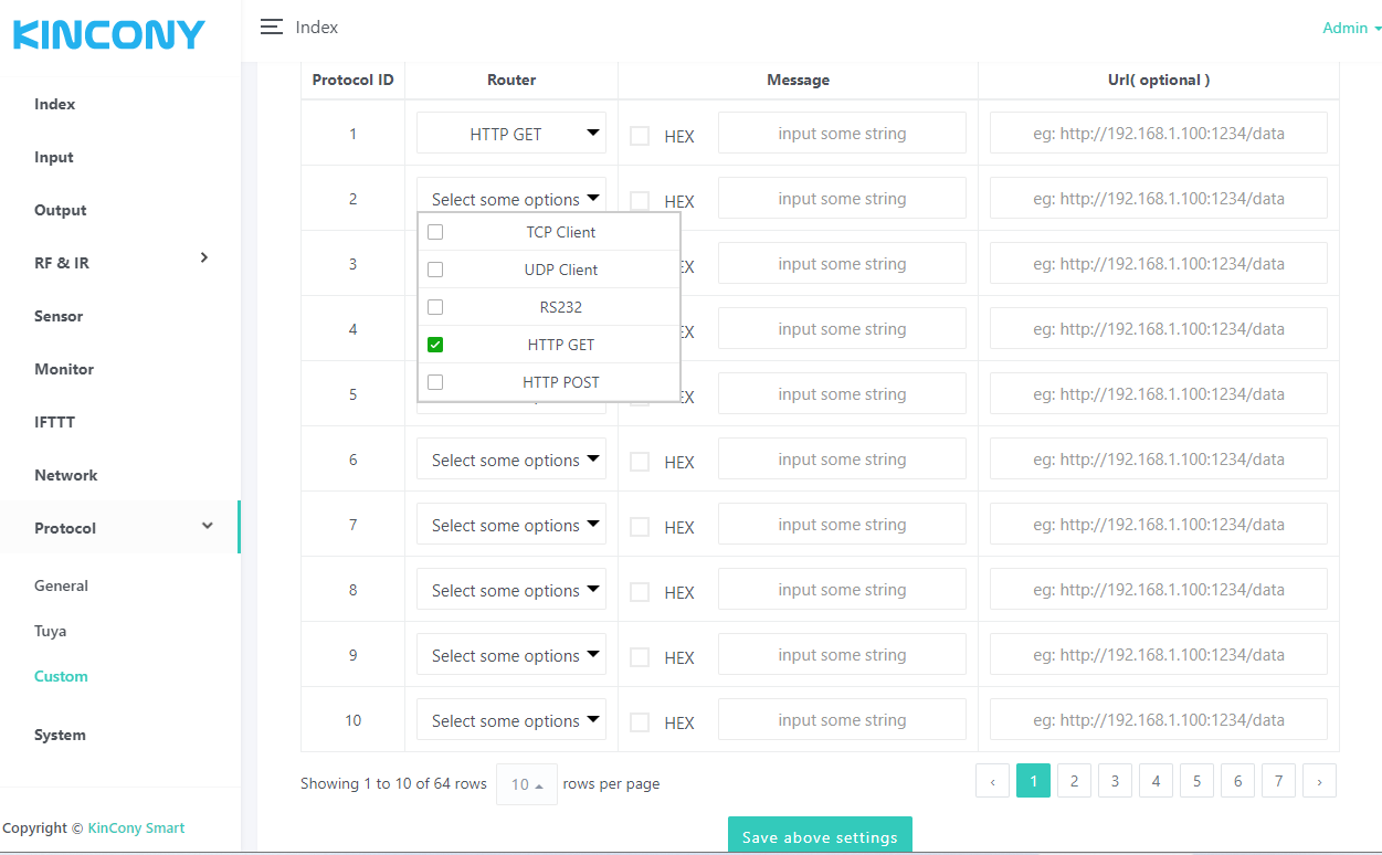
- Sending Custom Messages via Multiple Protocols
You can create and send messages using the following methods:
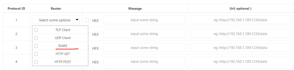
TCP Client, UDP Client, RS232, RS485, HTTP GET, HTTP POST
When the HEX option is not checked, your message will be sent as an ANSI string (plain text).
-
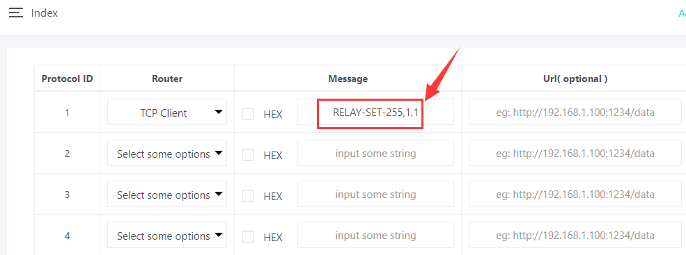
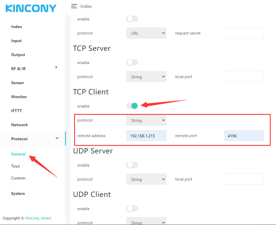
Example (TCP): Send a command to turn on relay 1 on another relay board at IP 192.168.1.215, port 4196.
The string you send: RELAY-SET-255,1,1
💡 Make sure the TCP Client protocol is enabled, and set the remote address to 192.168.1.215 and port to 4196 — this is the IP address of another relay board.
-
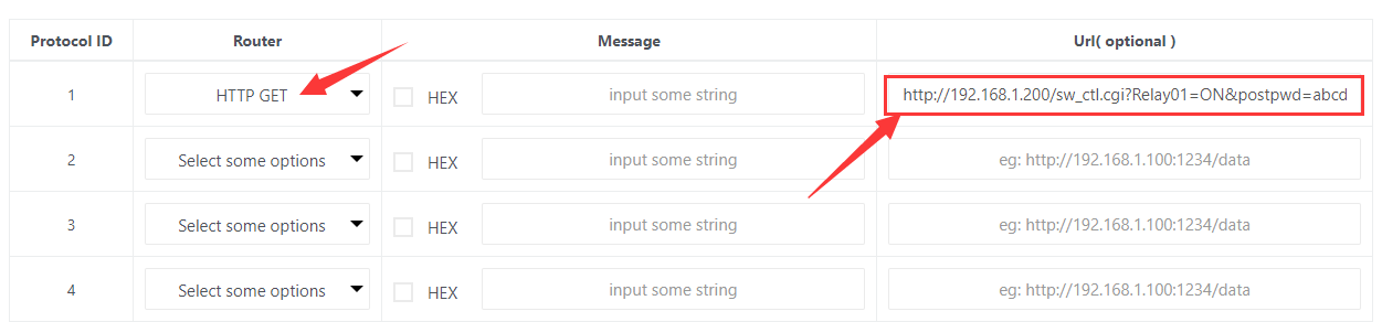
Example (HTTP GET): Send an HTTP command like
The image shows sending an HTTP GET command string:
- "http://192.168.1.200/sw_ctl.cgi?Relay01=ON&postpwd=abcd"
If you need to add extra information along with the HTTP command, simply fill in the "Message" edit box.
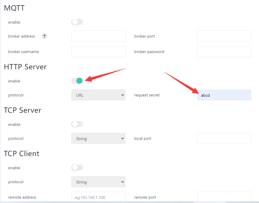
💡 Please enable the HTTP Server protocol and set a request secret to protect your commands from unauthorised access.
- Apple HomeKit Integration
You can make your board appear as a native device in Apple’s Home app.
-
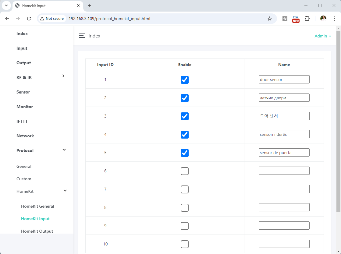
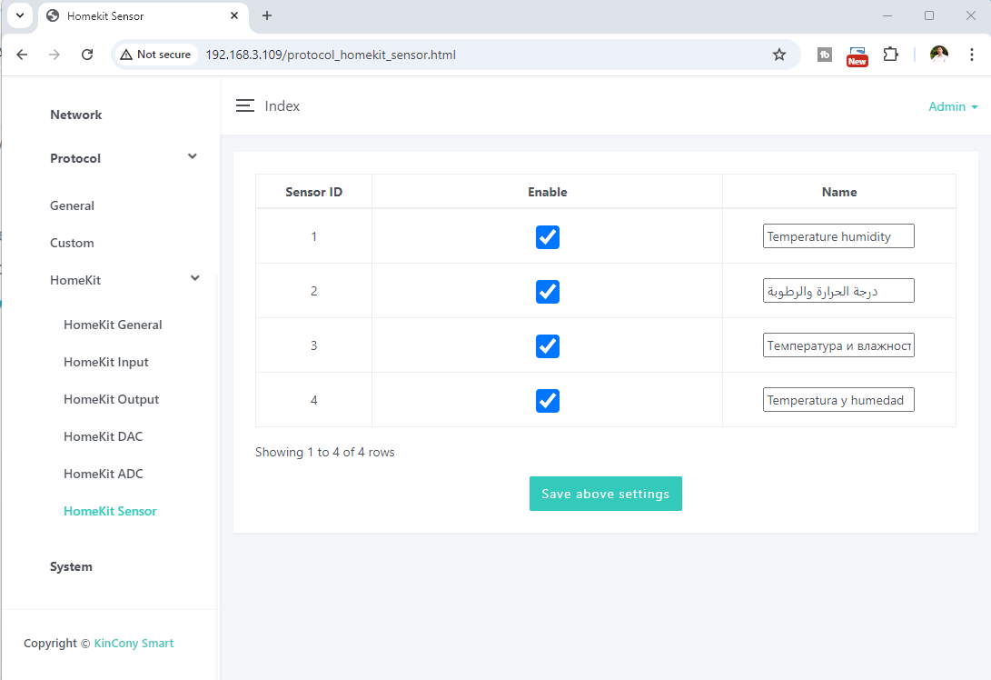
Configuration page – Set a custom name for each device (inputs, outputs, DAC, ADC, sensors).
-
Enable devices – Tick the checkboxes for the features you want to expose to HomeKit.
-
Auto-discovery – After completing settings on the INPUT, OUTPUT, DAC, ADC, and SENSOR webpages, simply enable the button. Your iPhone will automatically discover the KinCony device in the HomeKit app.
💡 When adding a device from an iPhone/iPad, the default pairing code is 11122333.
- RS485 Support
If your board has an RS485 interface, the option will automatically appear in the list, allowing you to use it for custom protocol messaging.
- Loxone Miniserver Integration
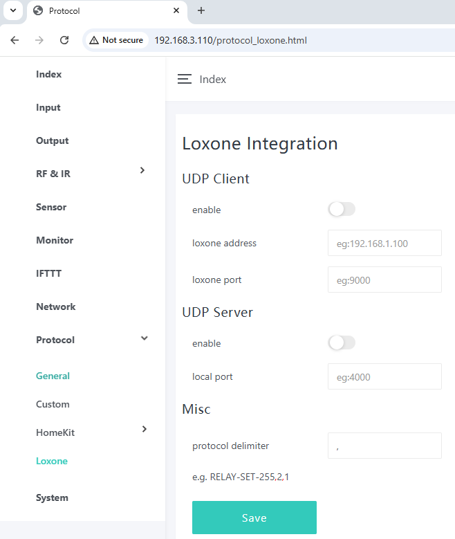
A dedicated webpage is available for Loxone Miniserver integration.
- WS2812 RGBW LED Strip Control
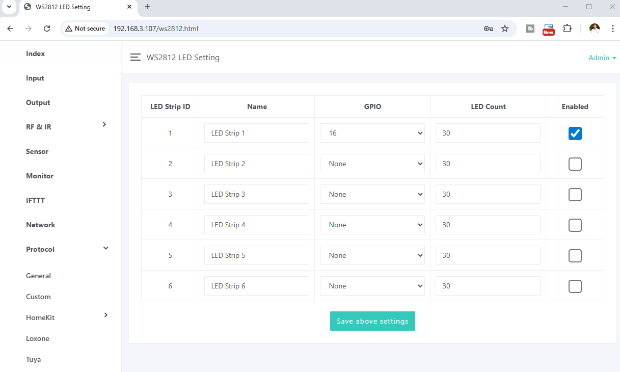
You can configure and control WS2812 RGBW LED strips directly from the board.
4.10 System
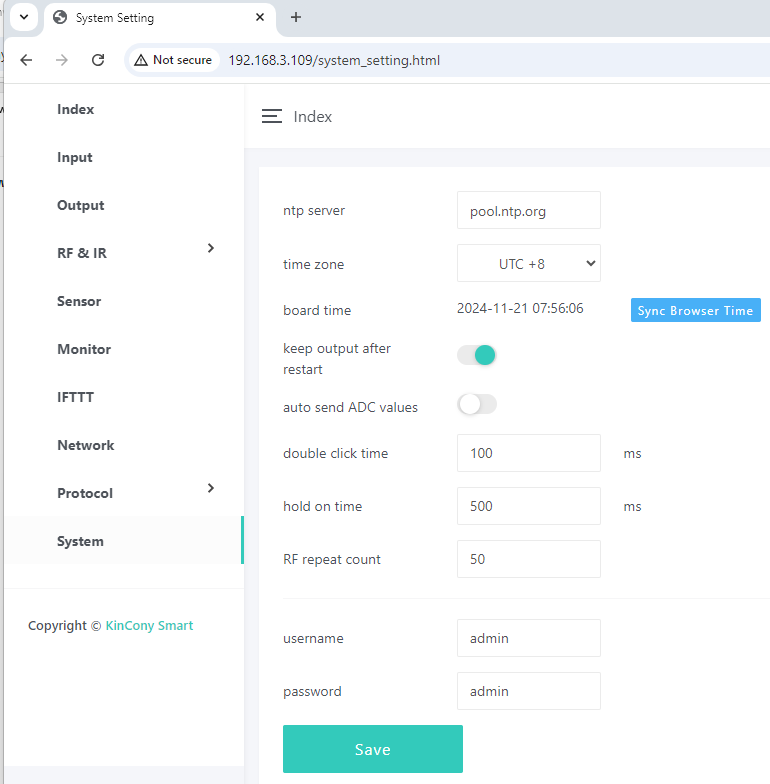
This page allows you to configure core system behaviours, manage time settings, reboot the board, and handle logs.
- Output Recovery After Power Failure
Keep output after restart – this option controls whether the board automatically restores the previous digital output states after a power failure.
-
Enabled – When power returns, outputs return to the state they were in before the power loss.
-
Disabled – Outputs start in a default (off) state after reboot.
- Automatic ADC Value Reporting
Auto send ADC values – when enabled, the board automatically sends the values of all analog input ports every 5 seconds via the active protocol (e.g., TCP, MQTT, etc.). This is useful for real‑time monitoring.
- Double Click Speed
Double click time – adjust this value to change how fast you need to double‑click (e.g., on a button or switch). A lower value means a faster double‑click is required.
- Hold‑on Time (Long Press Duration)
Hold on time – set the duration that defines a “long press”. This value determines how long you need to hold a button or input for it to be recognised as a hold action.
- Synchronising the Real‑Time Clock (RTC)
Click the “Sync Browser Time” button to write your web browser’s current time to the board’s RTC DS3231 clock.
- Once synchronised, the board can run IFTTT automations locally without an internet connection.
- The RTC keeps time locally, so automations can trigger based on real‑time schedules even when offline.
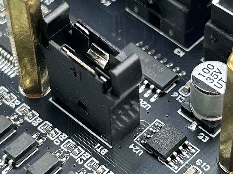
💡 To keep the clock running when the board is powered off, you must install a CR1220 battery. The board does not come with a battery pre‑installed (due to air shipping regulations).
- System Reboot Options
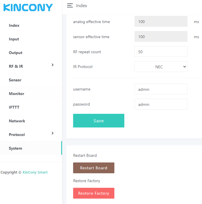
Two buttons are available at the bottom of the page:
-
Restart Board – Performs a soft reboot of the board. All settings are preserved.
-
Restore Factory – Resets all settings to their factory defaults and switches the Wi‑Fi mode to AP mode (so you can reconnect and reconfigure the board).
- Output Change Logging (SD Card)
Every time an OUTPUT state changes (e.g., a relay turns on or off), the change is automatically saved to a log file on the SD card. This helps you track events and debug automations.