


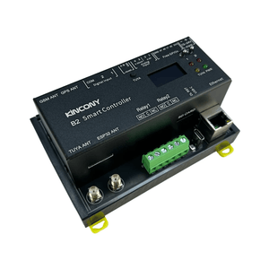
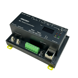
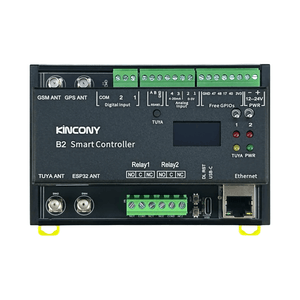
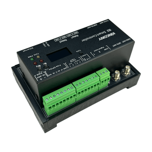
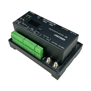
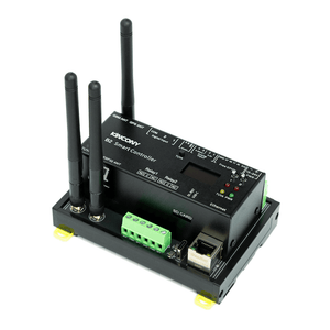
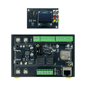
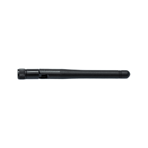
KinCony B2 2-Channel Smart Relay Controller
Frequently Bought Together
Version Options

Standard Version
The standard version without the cellular module. It provides the same core control capabilities via Wi-Fi, Ethernet, and RS485, ideal for stable wired network environments.

4G Version
Equipped with the SIM7600E 4G module, designed for cellular networks in Europe and Southeast Asia. It enables remote control and data transmission in areas without Wi-Fi or Ethernet access.
*Region-specific module. Please verify local carrier compatibility before ordering.
Features
- ESP32-S3 dual-core LX7 processor with 2.4 GHz Wi-Fi and Bluetooth LE
- Two SPDT relay outputs (COM/NO/NC) and two opto-isolated dry contact inputs with relay linkage control
- Four 16-bit analog inputs for 0–5 V and 4–20 mA sensors
- 100M Ethernet, isolated RS485, USB-C, 1-Wire GPIO, and I²C expansion
- Onboard RTC, I²C status display, microSD slot, and configuration buttons
- 12–24 V DC wide-voltage input and 35 mm DIN-rail mounting
- Optional SIM7600E 4G module for cellular connectivity
- KCS firmware supporting HTTP, MQTT, TCP, RS485 Modbus, and Tuya
- Home Assistant auto-discovery; compatible with KinCony Cloud, Loxone, Apple HomeKit
- Supports ESPHome, Tasmota, Arduino IDE, MicroPython, and ESP-IDF
Technical Specifications
| Category | Specification |
|---|---|
| Core Processor | ESP32-S3-WROOM-1U (N16R8, dual‑core 32‑bit Xtensa LX7) |
| Digital Outputs | 2× relays ▪ Contact: COM, NO, NC (1 × SPDT / Form C per channel) ▪ Max load: 10A @ 277VAC / 12A @ 125VAC, resistive load only, per channel |
| Analog Inputs | 4× ADS1115 16‑bit ADC ▪ 2× 0–5 VDC (A1, A2) ▪ 2× 4–20 mA (A3, A4) |
| Digital Inputs | 2× dry contact, opto‑isolated ▪ Cable length: up to 500 m (dependent on installation) |
| Digital I/O (GPIO) | ▪ 4× 1‑Wire interface (with pull‑up on PCB) |
| Wireless Connectivity | ▪ Wi‑Fi 2.4 GHz (802.11 b/g/n) ▪ Bluetooth |
| IoT Platform | Tuya‑compatible (via Wi‑Fi/Bluetooth) |
| Wired Connectivity | ▪ Ethernet: 100M RJ45 (IPv4/IPv6) ▪ RS485 ▪ USB‑C (power/programming) ▪ I²C (expansion) |
| Onboard Peripherals | ▪ RTC: DS3231 (battery socket on PCB) ▪ Display: SSD1306 I²C display ▪ Storage: microSD card socket (SPI bus) ▪ Buttons: 3× (ESP32 Reset / ESP32 Download / Tuya Config) ▪ Toggle Switches: 2× (Manual relay ON/OFF control) |
| Power Supply | 12-24 VDC |
| Dimensions | 124 × 83 × 56 mm |
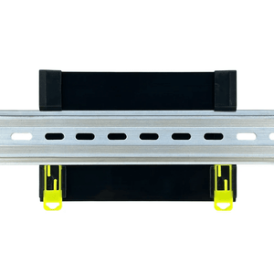
| Mounting | 35 mm DIN rail |
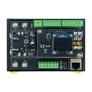
Onboard Components


-
1.ESP32-S3-WROOM-1U N16R8 Chip
Adopts ESP32-S3 series chip with Xtensa 32-bit LX7 dual-core processor, built in 16MB Flash and 8MB PSRAM -
2.Relay
High-quality mechanical relays for switching AC/DC loads -
3.Ethernet Port
100M RJ45 Ethernet port (IPv4/IPv6) -
4.USB-C Port
For firmware flashing only (cannot be used for power supply or data communication) -
5.ESP32 Reset Button
Reset button for ESP32 module -
6.ESP32 Download Button
Download button for ESP32 firmware flashing -
7.Relay Terminals
Screw terminals for relay output connection (COM / NO / NC) -
8.ESP32 Antenna Connector
SMA female connector, for Wi-Fi and Bluetooth wireless communication -
9.Tuya Antenna Connector
SMA female connector, for Tuya wireless communication -
10.RTC Battery Holder
Battery holder, maintains RTC timekeeping -
11.4G Antenna Connector
SMA female connector, for 4G cellular communication -
12.GPS Antenna Connector
SMA female connector, for GPS signal reception -
13.Digital Input Terminals
Screw terminals for dry contact digital input, opto-isolated
-
14.RS485 Terminals
Screw terminals for RS485 communication (A / B) -
15.Analog Input Terminals
Screw terminals for analog input (0–5 V / 4–20 mA) -
16.Free GPIO Terminals
Screw terminals for free GPIO access -
17.Power Supply Screw Terminal
Supports DC 12~24V wide voltage input -
18.RS485 Transceiver
RS485 transceiver chip for reliable serial communication -
19.Low-Dropout Linear Regulator (LDO)
Provides stable 3.3V output for onboard circuits -
20.SSD1306 OLED Display
I²C OLED display for showing IP address and connection status -
21.Tuya Config Button
Config button for Tuya network pairing -
22.Mini Toggle Switch (Manual Relay Backup)
Manual toggle switch for relay ON/OFF backup control -
23.Relay Status LED
Indicates relay ON/OFF status -
24.Power Status LED
PWR indicator, shows power supply status -
25.Tuya Status LED
Indicates Tuya connection status


-
26.ADS1115 Chip
16-bit ADC for high-precision analog input -
27.TVS Protection
Transient Voltage Suppressor, suppresses surge voltages and transient spikes -
28.Optocoupler Isolation
Prevents interference from external signals -
29.Reverse Polarity Protection
Protects the circuit from reverse power connection
-
30.W5500 Chip
Ethernet controller, extends 10/100 Mbps Ethernet via SPI interface -
31.Tuya Chip
Tuya wireless communication module -
32.SD Card Slot
Supports external TF card for storing images and files
Onboard Isolation & Protection

Voltage Regulator
Provides a stable 3.3V output, protecting the core chip from voltage fluctuations.
Reverse Polarity Protection
Prevents circuit damage caused by accidental reverse power connection.
Thicken Track
Reinforced copper traces for high-current paths, ensuring stable power delivery under heavy loads.
TVS Protection
Transient Voltage Suppressors absorb surge voltages and spikes, safeguarding sensitive components.
Optocoupler Isolation
Isolates external signals from the MCU, preventing interference and voltage spikes.
System Block Diagram

Outline Dimensions

Front View — Overall 124 × 83 mm / Aluminum cover 112 × 40 mm

Side View — Overall height 56 mm / Aluminum cover height 40 mm
Overall Length
124 mm
Overall Width
83 mm
Overall Height
56 mm
Mounting
35 mm DIN
Supports Arduino, Micropython, ESP-IDF development

Arduino IDE
Arduino IDE is an open-source electronic prototyping platform. It is convenient, flexible, and easy to start. With a simple learning curve, you can rapidly develop your projects.

MicroPython
MicroPython is a full implementation of Python 3 that runs directly on embedded hardware. It enables agile IoT development like Raspberry Pi Pico.

ESP-IDF
ESP-IDF is Espressif's official development framework. It provides low-level hardware access, maximum performance, and professional control for production-grade firmware.
For full firmware packages, demo codes and programming tutorials, please switch to the "Software Solution" tab above.
AC & DC Connection Diagrams
Onboard high-quality 2-channel relays, supporting RS485, Bluetooth, Wi-Fi, and 4G control.

AC Load Connection
Supported AC: Up to 277VAC @ 10A; up to 12A @ 125VAC.

DC Load Connection
Supported DC: Up to 30VDC; recommended ≤28VDC for resistive loads, 10A.
Enclosure Design

Front View — Aluminum Top Cover

Back View — Plastic Base with 35 mm DIN Rail Mount
Aluminum Top Cover Advantages
1. Premium Feel: Compared with ordinary ABS plastic cases, the aluminum top cover offers a more solid, high-end texture and better heat dissipation.
2. EMI Shielding: As a non-magnetic conductor, the aluminum top cover acts as a Faraday cage, protecting internal circuits from external electromagnetic radiation and preventing internal emissions.
Packing List


Note: GPS antenna is not included in the standard package.
Batch Customization Service
Support software and hardware customization including interface logo label case etc.
Label Customization
Logo, sticker, nameplate
Hardware Customization
PCB, interface, casing
Software Customization
Firmware, function, UI
Contact Customer Service
Send your customization requirements
One-to-One Technical Service
Professional evaluation and solution
Sign Contract & Start Project
Custom development and sample making
Sample Approval & Mass Production
Batch delivery after sample passes
B2 vs B4 vs B4M
Shared Features: ESP32-S3 N16R8 · DC 12–24V · 100M Ethernet + Wi-Fi + Bluetooth · DS3231 RTC · ADS1115 4× 16-bit ADC (0–5V & 4–20mA) · OLED display · microSD · RS485 · DIN-rail mounting · ESPHome / Home Assistant / Tuya support.
Key Differences
| Item | B2 (2CH Relay) | B4 (4CH Relay) | B4M (4CH MOSFET) |
|---|---|---|---|
| Output Type | Mechanical relay, COM / NO / NC (SPDT) | Mechanical relay, COM / NO only (no NC) | MOSFET DC switch (DC loads only) |
| Relay Quality | High-grade relay, 277V / 10A, with NC contact | Standard relay, 250V / 7A, COM / NO only | Not applicable (MOSFET switch) |
| Output Channels | 2× relay | 4× relay | 4× MOSFET |
| Load Capability | AC up to 277V / DC up to 30V, 10A per channel. Can switch AC mains. | AC up to 250V, 7A per channel. Can switch AC mains. | DC only (recommended 12–24V), 10A per channel. All channels share the same voltage. |
| 4G Module | Optional SIM7600E (Europe & Southeast Asia) | Not supported | Not supported |
| Digital Inputs | 2× opto-isolated DI (up to 500m) | 4× opto-isolated DI (up to 500m) | 4× opto-isolated DI (up to 500m) |
| GPIO | 4× 1-Wire | 7× 1-Wire | 4× 1-Wire + 3× free GPIO |
| Switching | Mechanical contact; limited lifespan, audible click, slow | Mechanical contact; limited lifespan, audible click, slow | No contact, silent, high-speed switching; supports PWM |
| Dimensions | 124 × 83 × 56 mm | 115 × 83 × 56 mm | 115 × 83 × 56 mm |
Which One Should You Choose?
Choose B2 if you need:
- To control AC mains loads with only 2 channels
- Higher-grade relay (277V / 10A) with NC contact
- Optional 4G cellular connectivity
- Dry-contact isolation for different external voltages
Choose B4 if you need:
- 4 channels of AC mains relay control
- Relay outputs with COM / NO only (no NC)
- More opto-isolated DI (4×) and 1-Wire GPIO (7×)
- Standard 250V / 7A relay capacity for typical AC loads
Choose B4M if you need:
- All loads are DC 12V / 24V (LED strips, solenoid valves, DC motors)
- 4 output channels + more DI + free GPIO
- High-frequency switching or PWM dimming, no relay clicking
- Lower cost, all-DC project
I. Firmware Options & Features
| Solution | Ideal For | Key Advantages |
|---|---|---|
| 1. KCS Firmware (Recommended) | Beginners / Zero-Code Users |
✔ Auto-detects Home Assistant via MQTT (zero config) ✔ Works with Tuya App + Alexa/Google Voice Control ✔ Local IFTTT automation (no internet needed) ✔ 2-year free KinCony Cloud (official store only) ✔ Apple HomeKit support for Siri ✔ Supports Loxone Miniserver integration ✔ Multi-protocol: HTTP, MQTT, Modbus (RS485/TCP), BACnet, DMX512 |
| 2. ESPHome Firmware | Home Assistant Enthusiasts |
✔ Full open-source customization ✔ Official ESPHome device support for B2 ✔ Web UI + deep HA integration ✔ Full YAML examples available |
| 3. Tasmota Firmware | Open-Source Community |
✔ Massive plugin ecosystem ✔ MQTT / Web control + rule engine |
| 4. Arduino / ESP-IDF Custom Code | Developers |
✔ Full Arduino demos provided ✔ Supports MicroPython / ESP-IDF |
| 5. Hybrid Setup (Best Practice) | Advanced Users | Tuya App (remote via internet) + Home Assistant (local via LAN) — Security + convenience |
II. Technical Resources
Direct links to pin definitions, ESPHome configurations, Arduino demo source codes, and KCS firmware. All open-source and maintained on GitHub.
| Resource | Link |
|---|---|
| KCS Firmware | kcs_firmware/B2/ |
| Pin Definitions | B2_pin_definition.md |
| Arduino Demos | B2/ (11 examples) |
| ESPHome Configuration | Official ESPHome B2 device page |
III. Getting Started Guide
Step 1: Flash Firmware
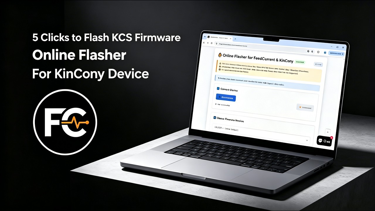
We recommend using the Online Flasher — no driver installation required, works entirely in your browser. Alternatively, follow the Quick Start Guide for manual flashing with the ESP32 desktop tool.
Step 2: Connect & Configure
Power on the board, connect via Ethernet or Wi-Fi, and access the web configuration interface. For detailed configuration, see the KCS Firmware User Guide.
Step 3: Integrate
Enable MQTT auto-discovery in Home Assistant, or pair with Tuya App for voice control.
IV. Video Tutorial: How to Flash KCS Online
No Drivers Needed, No Complex Setup—Flash Directly within Your Browser in 1 Minute!
Looking for software solutions for other products?
View All Product Software Solutions →